Chapter: 11th Physics : UNIT 5 : Motion of System of Particles and Rigid Bodies
Torque and Definition of Torque
Definition of Torque
Torque is defined as the moment of the external applied force about a point or axis of rotation. The expression for torque is,

where, ![]() is the position vector of the point where the force
is the position vector of the point where the force ![]() is acting on the body as shown in Figure 5.4.
is acting on the body as shown in Figure 5.4.
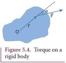
Here, the product of ![]() and
and ![]() is called the vector product or cross product. The vector product of two vectors results in another vector that is perpendicular to both the vectors (refer Section 2.5.2). Hence, torque
is called the vector product or cross product. The vector product of two vectors results in another vector that is perpendicular to both the vectors (refer Section 2.5.2). Hence, torque ![]() ) is a vector quantity.
) is a vector quantity.
Torque has a magnitude ( rFsinθ ) and direction perpendicular to ![]() and
and ![]() . Its unit is N m.
. Its unit is N m.

Here, θ is the angle between ![]() and
and ![]() , and nˆ is the unit vector in the direction of
, and nˆ is the unit vector in the direction of ![]() . Torque (
. Torque (![]() ) is sometimes called as a pseudo vector as it needs the other two vectors
) is sometimes called as a pseudo vector as it needs the other two vectors ![]() and
and ![]() for its existence.
for its existence.
The direction of torque is found using right hand rule. This rule says that if fingers of right hand are kept along the position vector with palm facing the direction of the force and when the fingers are curled the thumb points to the direction of the torque. This is shown in Figure 5.5.
The direction of torque helps us to find the type of rotation caused by the torque. For example, if the direction of torque is out
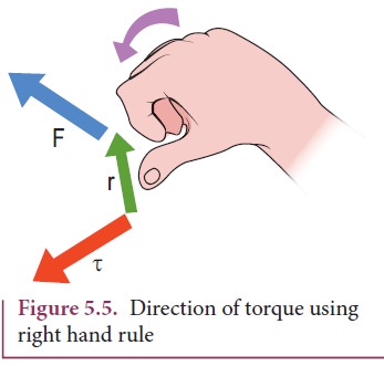
of the paper, then the rotation produced by the torque is anticlockwise. On the other hand, if the direction of the torque is into the paper, then the rotation is clockwise as shown in Figure 5.6.
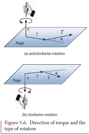
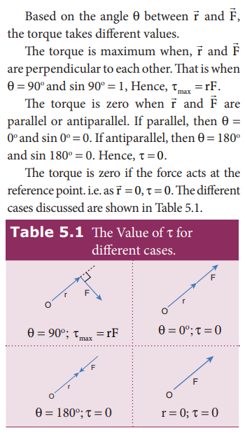
In many cases, the direction and magnitude of the torque are found separately. For direction, we use the vector rule or right hand rule. For magnitude, we use scalar form as,

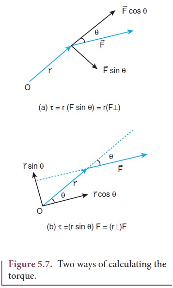
The expression for the magnitude of torque can be written in two different ways by associating sin θ either with r or F in the following manner.

Here, (F sinθ) is the component of ![]() perpendicular to
perpendicular to ![]() . Similarly, ( r sinθ) is the component of
. Similarly, ( r sinθ) is the component of ![]() perpendicular to
perpendicular to ![]() . The two cases are shown in Figure 5.7.
. The two cases are shown in Figure 5.7.
Torque about an Axis
In the earlier sections, we have dealt with the torque about a point. In this section we will deal with the torque about an axis. Let us consider a rigid body capable of rotating about an axis AB as shown in Figure 5.8. Let the force F act at a point P on the rigid body. The force F may not be on the plane ABP. We can take the origin O at any random point on the axis AB.
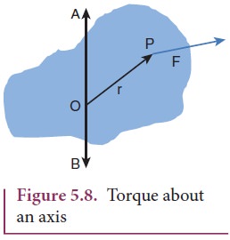
Th e torque of the force ![]() about O is,
about O is, ![]() =
= ![]() x
x![]() . Th e component of the torque along the axis is the torque of
. Th e component of the torque along the axis is the torque of ![]() about the axis. To find it, we should first find the vector
about the axis. To find it, we should first find the vector ![]() = |
= |![]() x
x![]() | and then find the angle φ between
| and then find the angle φ between ![]() and AB. (Remember here,
and AB. (Remember here, ![]() is not on the plane ABP). Th e torque about AB is the parallel component of the torque along AB, which is |
is not on the plane ABP). Th e torque about AB is the parallel component of the torque along AB, which is | ![]() x
x![]() | cos φ. And the torque perpendicular to the axis AB is |
| cos φ. And the torque perpendicular to the axis AB is | ![]() x
x![]() | sin φ|.
| sin φ|.
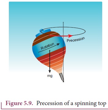
The torque about the axis will rotate the object about it and the torque perpendicular to the axis will turn the axis of rotation. When both exist simultaneously on a rigid body, the body will have a precession. One can witness the precessional motion in a spinning top when it is about to come to rest as shown in Figure 5.9.
Study of precession is beyond the scope of the higher secondary physics course. Hence, it is assumed that there are constraints to cancel the effect of the perpendicular components of the torques, so that the fixed position of the axis is maintained. Therefore, perpendicular components of the torque need not be taken into account.
Hereafter, for the calculation of torques on rigid bodies we will:
a. Consider only those forces that lie on planes perpendicular to the axis (and do not intersect the axis).
b. Consider position vectors which are perpendicular to the axis.
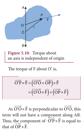
The torque of a force about an axis is independent of the choice of the origin as long as it is chosen on that axis itself. This can be shown as below.
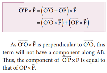
Let O be the origin on the axis AB, which is the rotational axis of a rigid body. F is the force acting at the point P. Now, choose another point O’ anywhere on the axis as shown in Figure 5.10.
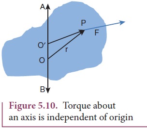
The torque of F about O’ is,
Torque and Angular Acceleration
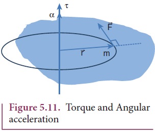
Let us consider a rigid body rotating about a fixed axis. A point mass m in the body will execute a circular motion about a fixed axis as shown in Figure 5.11. A tangential force ![]() acting on the point mass produces the necessary torque for this rotation. This force
acting on the point mass produces the necessary torque for this rotation. This force ![]() is perpendicular to the position vector
is perpendicular to the position vector ![]() of the point mass.
of the point mass.
The torque produced by the force on the point mass m about the axis can be written as,
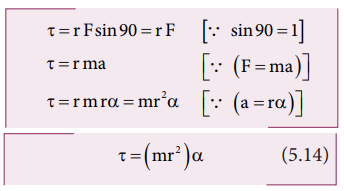
Hence, the torque of the force acting on the point mass produces an angular acceleration ( α) in the point mass about the axis of rotation.
In vector notation,

The directions of τ and α are along the axis of rotation. If the direction of τ is in the direction of α, it produces angular acceleration. On the other hand if, τ is opposite to α, angular deceleration or retardation is produced on the point mass.
The term mr2 in equations 5.14 and 5.15 is called moment of inertia (I) of the point mass. A rigid body is made up of many such point masses. Hence, the moment of inertia of a rigid body is the sum of moments of inertia of all such individual point masses that constitute the body ( I = ∑mi ri2 ). Hence, torque for the rigid body can be written as,

We will learn more about the moment of inertia and its significance for bodies with different shapes in section 5.4.
Solved Example Problems for Torque
Example 5.7
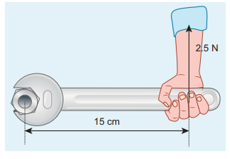
If the force applied is perpendicular to the handle of the spanner as shown in the diagram, find the (i) torque exerted by the force about the center of the nut, (ii) direction of torque and (iii) type of rotation caused by the torque about the nut.
Solution
Arm length of the spanner, r = 15 cm = = 15×10−2m
Force, F = 2.5 N
Angle between r and F, θ = 90o

(i) Torque, τ θ = rF sin
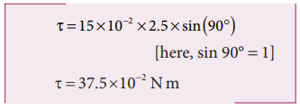
(ii) As per the right hand rule, the direction of torque is out of the page.
(iii) The type of rotation caused by the torque is anticlockwise.
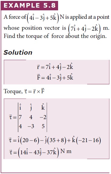
Example 5.8
Example 5.9
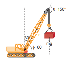
A crane has an arm length of 20 m inclined at 30o with the vertical. It carries a container of mass of 2 ton suspended from the top end of the arm. Find the torque produced by the gravitational force on the container about the point where the arm is fixed to the crane. [Given: 1 ton = 1000 kg; neglect the weight of the arm. g = 10 ms-2]
Solution
The force F at the point of suspension is due to the weight of the hanging mass.

We can solve this problem by three different methods.
Method – I
The angle (θ) between the arm length (r) and the force (F) is, θ = 150o
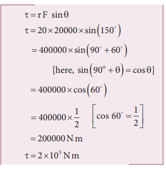
The torque (τ) about the fixed point of the arm is,
Method – II
Let us take the force and perpendicular distance from the point where the arm is fixed to the crane.
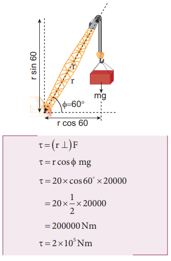
Method – III
Let us take the distance from the fixed point and perpendicular force.
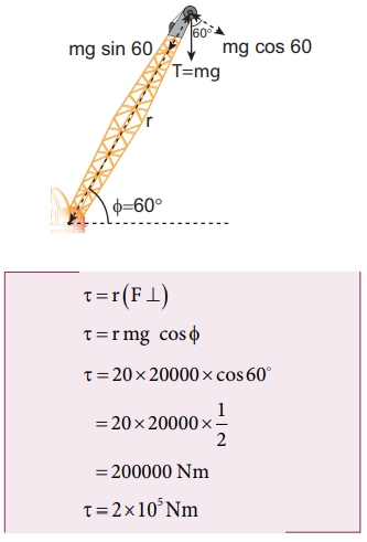
All the three methods, give the same answer
Solved Example Problems for Torque about an Axis
Example 5.10
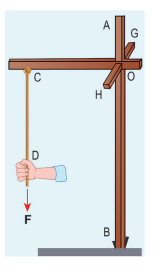
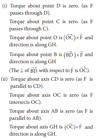
Three mutually perpendicular beams AB, OC, GH are fixed to form a structure which is fixed to the ground firmly as shown in the Figure. One string is tied to the point C and its free end D is pulled with a force F. Find the magnitude and direction of the torque produced by the force,
i. about the points D, C, O and B
ii. about the axes CD, OC, AB and GH.
Solution
The torque of a force about an axis is independent of the choice of the origin as long as it is chosen on that axis itself. Th is can be shown as below.
Let O be the origin on the axis AB, which is the rotational axis of a rigid body. F is the force acting at the point P. Now, choose another point O’ anywhere on the axis as shown in Figure 5.10.
Related Topics