Thermodynamics - CarnotŌĆÖs ideal heat engine | 11th Physics : UNIT 8 : Heat and Thermodynamics
Chapter: 11th Physics : UNIT 8 : Heat and Thermodynamics
CarnotŌĆÖs ideal heat engine
CarnotŌĆÖs ideal heat engine
In the previous section we have seen that the heat engine cannot have 100% efficiency. What is the maximum possible efficiency can a heat engine have?. In the year 1824 a young French engineer Sadi Carnot proved that a certain reversible engine operated in cycle between hot and cold reservoir can have maximum efficiency. This engine is called Carnot engine.
A reversible heat engine operating in a cycle between two temperatures in a particular way is called a Carnot Engine.
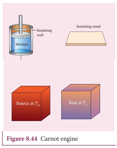
The carnot engine has four parts which are given below.
i. Source: It is the source of heat maintained at constant high temperature TH. Any amount of heat can be extracted from it, without changing its temperature.
ii. Sink: It is a cold body maintained at a constant low temperature TL. It can absorb any amount of heat.
iii. Insulating stand: It is made of perfectly non-conducting material. Heat is not conducted through this stand.
iv. Working substance: It is an ideal gas enclosed in a cylinder with perfectly non-conducting walls and perfectly conducting bottom. A non-conducting and frictionless piston is fitted in it.
The four parts are shown in the following Figure 8.44
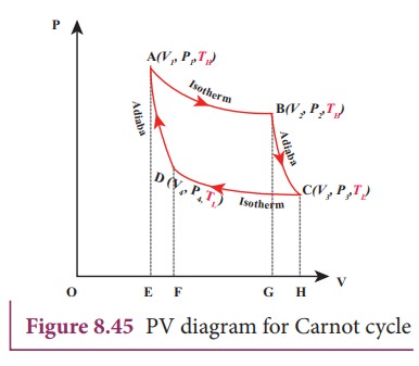
CarnotŌĆÖs cycle:
The working substance is subjected to four successive reversible processes forming what is called CarnotŌĆÖs cycle.
Let the initial pressure, volume of the working substance be P1,V1.
Step A to B: Quasi-static isothermal expansion from (P1,V1,TH) to (P2,V2,TH):
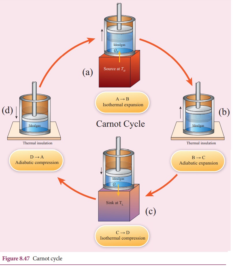
The cylinder is placed on the source. The heat (QH) flows from source to the working substance (ideal gas) through the bottom of the cylinder. Since the process is isothermal, the internal energy of the working substance will not change. The input heat increases the volume of the gas. The piston is allowed to move out very slowly(quasi-statically). It is shown in the figure 8.47(a).
W1 is the work done by the gas in expanding from volume V1 to volume V2 with a decrease of pressure from P1 to P2. This is represented by the P-V diagram along the path AB as shown in the Figure 8.45.
Then the work done by the gas (working substance) is given by
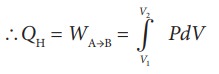
Since the process occurs quasi-statically, the gas is in equilibrium with the source till it reaches the final state. The work done in the isothermal expansion is given by the equation (8.34)
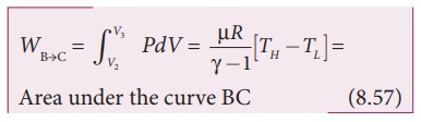
Step B to C: Quasi-static adiabatic expansion from (P2,V2,TH) to (P3,V3,TL)
The cylinder is placed on the insulating stand and the piston is allowed to move out. As the gas expands adiabatically from volume V2 to volume V3 the pressure falls from P2 to P3. The temperature falls to TL. This adiabatic expansion is represented by curve BC in the P-V diagram. This adiabatic process also occurs quasi-statically and implying that this process is reversible and the ideal gas is in equilibrium throughout the process. It is shown in the figure 8.47(b). From the equation (8.42)
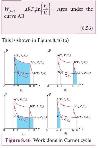
The work done by the gas in an adiabatic expansion is given by,
This is shown in Figure 8.46 (b)
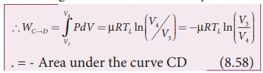
StepŌĆåCŌĆåŌåÆŌĆåD: Quasi-static isothermal compression from (P3,V3,TL) to (P4,V4,TL): It is shown in the figure 8.47(c)
The cylinder is placed on the sink and the gas is isothermally compressed until the pressure and volume become P4 and V4 respectively. This is represented by the curve CD in the PV diagram as shown in Figure 8.45. Let WCŌåÆD be the work done on the gas. According to first law of thermodynamics
This is shown in Figure 8.46 (c)
Here V3 is greater than V4. So the work done is negative, implying work is done on the gas.
StepŌĆåDŌåÆA: Quasi-static adiabatic compression from (P4,V4,TL) to (P1,V1,TH): It is shown in the figure 8.47(d)
The cylinder is placed on the insulating stand again and the gas is compressed adiabatically till it attains the initial pressure P1, volume V 1 and temperature T H. This is shown by the curve DA in the P-V diagram.
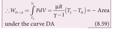
In the adiabatic compression also work is done on the gas so it is negative, as is shown in Figure 8.46 (d)
Let ŌĆśWŌĆÖ be the net work done by the working substance in one cycle
Ōł┤W=Work done by the gas ŌĆō work done on the gas
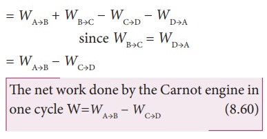
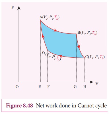
Equation (8.60) shows that the net work done by the working substance in one cycle is equal to the area (enclosed by ABCD) of the P-V diagram (Figure 8.48)
It is very important to note that after one cycle the working substance returns to the initial temperature TH. This implies that the change in internal energy of the working substance after one cycle is zero.
Related Topics