Explanation with Solved Example Problems - Capacitor in series and parallel | 12th Physics : Electrostatics
Chapter: 12th Physics : Electrostatics
Capacitor in series and parallel
Capacitor
in series and parallel
(i) Capacitor in series
Consider three capacitors of capacitance C1, C2 and C3 connected in series with a battery of voltage V as shown in the Figure 1.60 (a).
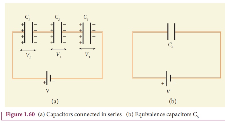
As soon as the battery is connected to the capacitors in series, the electrons of charge –Q are transferred from
negative terminal to the right plate of C3 which pushes the
electrons of same amount -Q from left plate of C3 to the right plate
of C2 due to electrostatic induction. Similarly, the left plate of C2
pushes the charges of –Q to the right plate of C1 which induces the
positive charge +Q on the left plate of C1. At the same time,
electrons of charge –Q are transferred from left plate of C1 to
positive terminal of the battery.
By these processes, each
capacitor stores the same amount of charge Q. The capacitances of the
capacitors are in general different, so that the voltage across each capacitor
is also different and are denoted as V1, V2 and V3
respectively.
The total voltage across
each capacitor must be equal to the voltage of the battery.
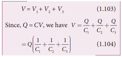
If three capacitors in
series are considered to form an equivalent single capacitor Cs
shown in Figure 1.60(b), then we have V=Q/Cs. Substituting this expression into
equation (1.104), we get
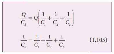
Thus, the inverse of the
equivalent capacitance CS of three capacitors connected in series is
equal to the sum of the inverses of each capacitance. This equivalent
capacitance CS is always less than the smallest individual
capacitance in the series.
(ii) Capacitance in parallel
Consider three
capacitors of capacitance C1, C2 and C3
connected in parallel with a battery of voltage V as shown in Figure 1.61 (a).
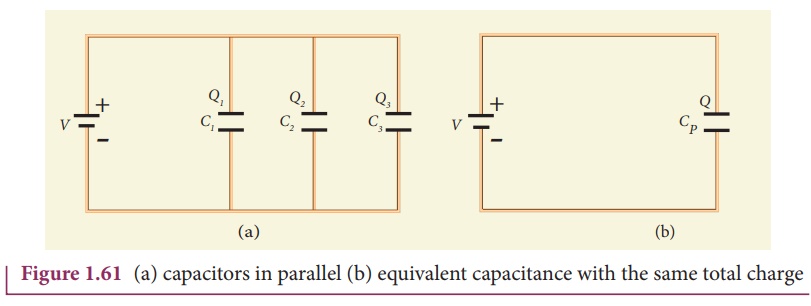
Since corresponding
sides of the capacitors are connected to the same positive and negative
terminals of the battery, the voltage across each capacitor is equal to the
battery’s voltage. Since capacitance of the capacitors is different, the charge
stored in each capacitor is not the same. Let the charge stored in the three
capacitors be Q1, Q2, and Q3 respectively.
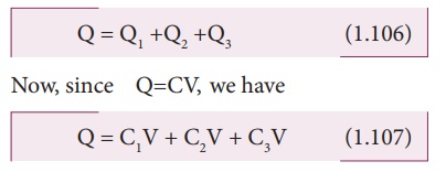
According to the law of conservation of total charge, the sum of these three
charges is equal to the charge Q transferred by the battery,
If these three
capacitors are considered to form a single capacitance CP which
stores the total charge Q as shown in the Figure 1.61(b), then we can write Q =
CPV. Substituting this in equation (1.107), we get
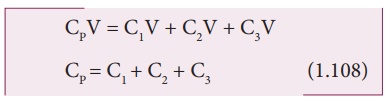
Thus, the equivalent
capacitance of capacitors connected in parallel is equal to the sum of the
individual capacitances.
The equivalent
capacitance CP in a parallel connection is always greater than the
largest individual capacitance. In a parallel connection, it is equivalent as
area of each capacitance adds to give more effective area such that total
capacitance increases.
EXAMPLE 1.22
Find the equivalent capacitance
between P and Q for the configuration shown below in the figure (a).
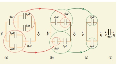
Solution
The capacitors 1 µF and 3µF are connected in parallel and 6µF and 2 µF are also separately connected in parallel. So these parallel combinations reduced to equivalent single capacitances in their respective positions, as shown in the figure (b).
Ceq = 1µF + 3µF = 4µF
Ceq = 6µF + 2µF = 8µF
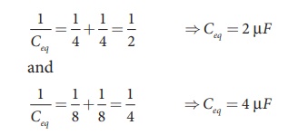
From the figure (b), we infer that
the two 4 µF capacitors are connected in series and the two 8 µF capacitors are
connected in series. By using formula for the series, we can reduce to their
equivalent capacitances as shown in figure (c).
From the figure (c), we infer that
2µF and 4µF are connected in parallel. So the equivalent capacitance is given
in the figure (d).
Ceq = 2µF + 4µF = 6µF
Thus the combination of capacitances
in figure (a) can be replaced by a single capacitance 6 µF.
Related Topics