Principle, Construction, Working Principle, Diagram - Single phase AC generator | 12th Physics : Electromagnetic Induction and Alternating Current
Chapter: 12th Physics : Electromagnetic Induction and Alternating Current
Single phase AC generator
Single phase AC generator
In a single phase AC generator, the armature conductors are connected in series so as to form a single circuit which generates a single-phase alternating emf and hence it is called single-phase alternator.
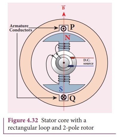
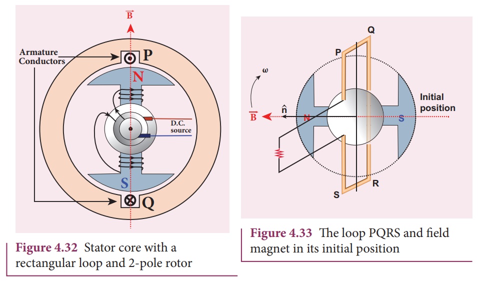
The simplified version of a AC generator is discussed here. Consider a stator core consisting of 2 slots in which 2 armature conductors PQ and RS are mounted to form single-turn rectangular loop PQRS as shown in Figure 4.33. Rotor has 2 salient poles with field windings which can be magnetized by means of DC source.
Working
The loop PQRS is stationary and is perpendicular to the plane of the paper. When field windings are excited, magnetic field is produced around it. The direction of magnetic field passing through the armature core is shown in Figure 4.33. Let the field magnet be rotated in clockwise direction by the prime mover. The axis of rotation is perpendicular to the plane of the paper.
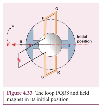
Assume that initial position of the field magnet is horizontal. At that instant, the direction of magnetic field is perpendicular to the plane of the loop PQRS. The induced emf is zero (Refer case (iii) of section 4.4). This is represented by origin O in the graph between induced emf and time angle (Figure 4.34).
When field magnet rotates through 90°, magnetic field becomes parallel to PQRS. The induced emfs across PQ and RS would become maximum. Since they are connected in series, emfs are added up and the direction of total induced emf is given by Fleming’s right hand rule.
Care has to be taken while applying this rule; the thumb indicates the direction of the motion of the conductor with respect to field. For clockwise rotating poles, the conductor appears to be rotating anti-clockwise. Hence, thumb should point to the left. The direction of the induced emf is at right angles to the plane of the paper. For PQ, it is downwards and for RS upwards. Therefore, the current flows along PQRS. The point A in the graph represents this maximum emf.
For the rotation of 180° from the initial position, the field is again perpendicular to PQRS and the induced emf becomes zero. This is represented by point B.
The field magnet becomes again parallel to PQRS for 270° rotation of field magnet. The induced emf is maximum but the direction is reversed. Thus the current flows along SRQP. This is represented by point C.
On completion of 360°, the induced emf becomes zero and is represented by the point D. From the graph, it is clear that emf induced in PQRS is alternating in nature.
Therefore, when field magnet completes one rotation, induced emf in PQRS finishes one cycle. For this construction, the frequency of the induced emf depends on the speed at which the field magnet rotates.
Related Topics