Phasor diagram, Circuit Diagram, Formula, Solved Example Problems | Alternating Current (AC) - AC circuit containing only an inductor | 12th Physics : Electromagnetic Induction and Alternating Current
Chapter: 12th Physics : Electromagnetic Induction and Alternating Current
AC circuit containing only an inductor
AC circuit containing only an inductor
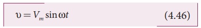
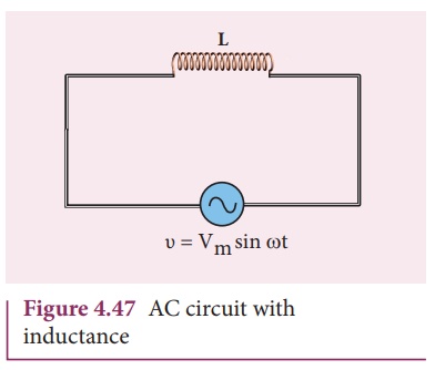
Consider a circuit containing a pure inductor of inductance L connected across an alternating voltage source (Figure 4.47). The alternating voltage is given by the equation.
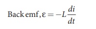
The alternating current flowing through the inductor induces a self-induced emf or back emf in the circuit. The back emf is given by
By applying Kirchoff’s loop rule to the purely inductive circuit, we get
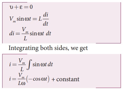
The integration constant in the above equation is independent of time. Since the voltage in the circuit has only time dependent part, we can set the time independent part in the current (integration constant) into zero.
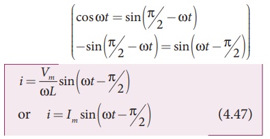
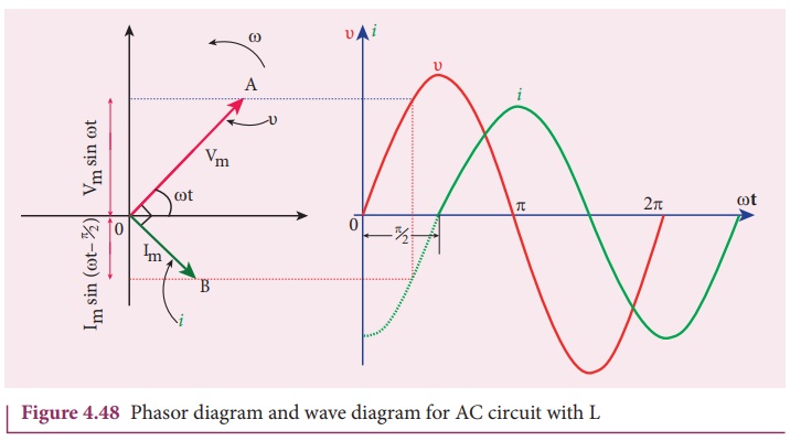
where Vm / ωL =Im , the peak value of the alternating current in the circuit. From equation (4.46) and (4.47), it is evident that current lags behind the applied voltage by π/2 in an inductive circuit. This fact is depicted in the phasor diagram. In the wave diagram also, it is seen that current lags the voltage by 90º (Figure 4.48).
Inductive reactance XL
The peak value of current Im is given by Im = Vm / ωL . Let us compare this equation with Im = Vm / R from resistive circuit. The quantity ωL plays the same role as the resistance in resistive circuit. This is the resistance offered by the inductor, called inductive reactance (XL). It is measured in ohm.![]()
X L = ωL
The inductive reactance (XL) varies directly as the frequency.
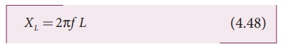
where f is the frequency of the alternating current. For a steady current, f = 0. Therefore, XL = 0. Thus an ideal inductor offers no resistance to steady DC current.
EXAMPLE 4.20
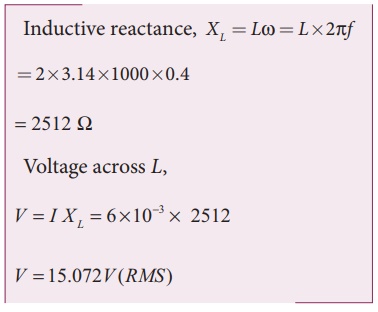
A 400 mH coil of negligible resistance is connected to an AC circuit in which an effective current of 6 mA is flowing. Find out the voltage across the coil if the frequency is 1000 Hz.
Solution
L = 400 x 10-3 H; Ieff = 6 x 10⁻³A
f = 1000 Hz
Related Topics