Principle, Construction, Working Principle, Diagram, Advantages - AC Generator | 12th Physics : Electromagnetic Induction and Alternating Current
Chapter: 12th Physics : Electromagnetic Induction and Alternating Current
AC Generator
AC GENERATOR
1. Introduction
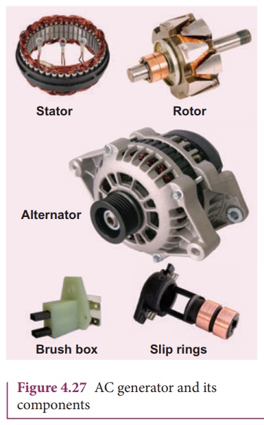
AC generator or
alternator is an energy conversion device. It converts mechanical energy used
to rotate the coil or field magnet into electrical energy. Alternator produces
a large scale electrical power for use in homes and industries. AC generator
and its components are shown in Figure 4.27.
2. Principle
Alternators work on the
principle of electromagnetic induction. The relative motion between a conductor
and a magnetic field changes the magnetic flux linked with the conductor which
in turn, induces an emf. The magnitude of the induced emf is given by Faraday’s
law of electromagnetic induction and its direction by Fleming’s right hand
rule.
3. Construction
Alternator consists of
two major parts, namely stator and rotor. As their names suggest, stator is
stationary while rotor rotates inside the stator. In any standard construction
of commercial alternators, the armature winding is mounted on stator and the
field magnet on rotor.
The construction details
of stator, rotor and various other components involved in them are given below.
i) Stator
The stationary part
which has armature windings mounted in it is called stator. It has three
components, namely stator frame, stator core and armature winding.
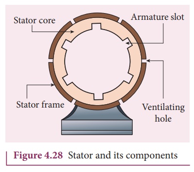
Stator frame
This is the outer frame
used for holding stator core and armature windings in proper position. Stator
frame provides best ventilation with the help of holes provided in the frame
itself (Figure 4.28).
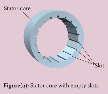
Stator core
Stator core or armature
core is made up of iron or steel alloy. It is a hollow cylinder and is
laminated to minimize eddy current loss. The slots are cut on inner surface of
the core to accommodate armature windings.
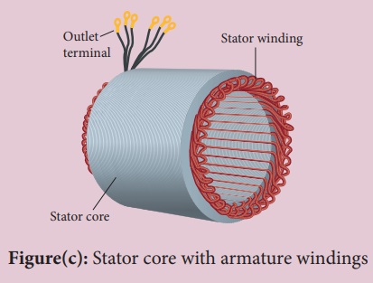
Armature winding
Armature winding is the
coil, wound on slots provided in the armature core. One or more than one coil
may be employed, depending on the type of alternator.
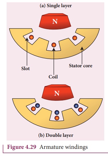
Two types of windings
are commonly used. They are i) single-layer winding and ii) double-layer
winding. In single-layer winding, a slot is occupied by a coil as a single layer.
But in double-layer winding, the coils are split into two layers such as top
and bottom layers (Figure 4.29).
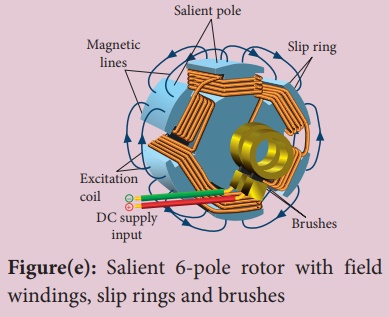
ii) Rotor
Rotor contains magnetic
field windings. The magnetic poles are magnetized by DC source. The ends of
field windings are connected to a pair of slip rings, attached to a common
shaft about which rotor rotates. Slip rings rotate along with rotor. To
maintain connection between the DC source and field windings, two brushes are
used which continuously slide over the slip rings.
There are 2 types of
rotors used in alternators i) salient pole rotor and ii) cylindrical pole
rotor.
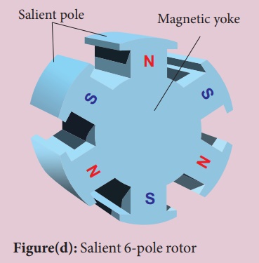
Salient pole rotor
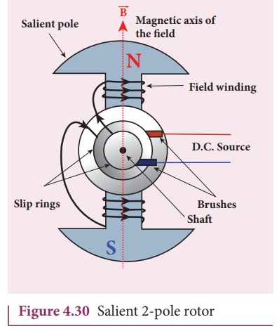
The word salient means
projecting. This rotor has a number of projecting poles having their bases riveted
to the rotor. It is mainly used in low-speed alternators. The salient 2-pole
rotor is shown in the Figure 4.30.
Cylindrical pole rotor
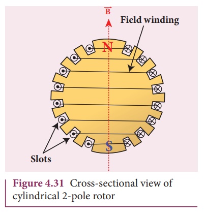
This rotor consists of a
smooth solid cylinder. The slots are cut on the outer surface of the cylinder
along its length. It is suitable for very high speed alternators (Figure 4.31).
The frequency of
alternating emf induced is directly proportional to the rotor speed. In order
to maintain the frequency constant, the rotor must run at a constant speed.
These are standard
construction details of alternators. Based on the type of alternator being
constructed, the details like number of poles, pole type, number of coils and
type of windings would change from one another.
We will discuss the
construction and working of two examples, namely single phase and three phase
AC generators in the following sections.
Construction of AC generator
Alternator consists of two major parts, namely stator and rotor. (This box is given for better understanding of constructional details)
i) Stator
Stator has three components, namely stator frame, stator core and armature winding.
ii) Rotor
Rotor contains magnetic field windings, slip rings and brushes mounted on the same shaft.

4. Advantages of stationary armature-rotating field alternator
Alternators are
generally high current and high voltage machines. The stationary armature-rotating
field construction has many advantages. A few of them include:
1) The current is
drawn directly from fixed terminals on the stator without the use of brush
contacts.
2) The insulation
of stationary armature winding is easier.
3) The number of sliding
contacts (slip rings) is reduced. Moreover, the sliding contacts are used for
low-voltage DC Source.
4) Armature
windings can be constructed more rigidly to prevent deformation due to any
mechanical stress.
5. Single phase AC generator
In a single phase AC
generator, the armature conductors are connected in series so as to form a
single circuit which generates a single-phase alternating emf and hence it is
called single-phase alternator.
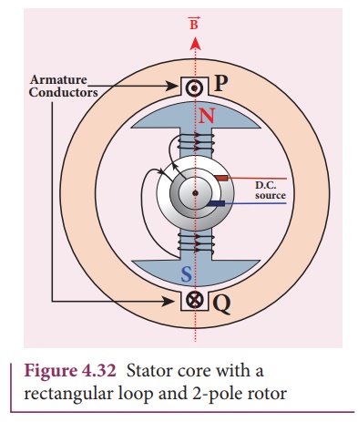
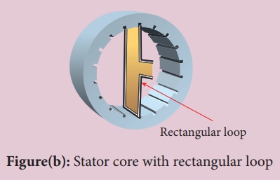
The simplified version
of a AC generator is discussed here. Consider a stator core consisting of 2
slots in which 2 armature conductors PQ and RS are mounted to form single-turn
rectangular loop PQRS as shown in Figure 4.33. Rotor has 2 salient poles with
field windings which can be magnetized by means of DC source.
Working
The loop PQRS is
stationary and is perpendicular to the plane of the paper. When field windings
are excited, magnetic field is produced around it. The direction of magnetic
field passing through the armature core is shown in Figure 4.33. Let the field
magnet be rotated in clockwise direction by the prime mover. The axis of
rotation is perpendicular to the plane of the paper.
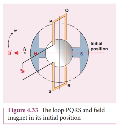
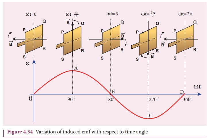
Assume that initial
position of the field magnet is horizontal. At that instant, the direction of
magnetic field is perpendicular to the plane of the loop PQRS. The induced emf
is zero (Refer case (iii) of section 4.4). This is represented by origin O in
the graph between induced emf and time angle (Figure 4.34).
When field magnet
rotates through 90°, magnetic field becomes parallel to PQRS. The induced emfs
across PQ and RS would become maximum. Since they are connected in series, emfs
are added up and the direction of total induced emf is given by Fleming’s right
hand rule.
Care has to be taken while
applying this rule; the thumb indicates the direction of the motion of the
conductor with respect to field. For clockwise rotating poles, the conductor
appears to be rotating anti-clockwise. Hence, thumb should point to the left.
The direction of the induced emf is at right angles to the plane of the paper.
For PQ, it is downwards and for RS upwards. Therefore, the current flows along
PQRS. The point A in the graph represents this maximum emf.
For the rotation of 180°
from the initial position, the field is again perpendicular to PQRS and the
induced emf becomes zero. This is represented by point B.
The field magnet becomes
again parallel to PQRS for 270° rotation of field magnet. The induced emf is
maximum but the direction is reversed. Thus the current flows along SRQP. This
is represented by point C.
On completion of 360°,
the induced emf becomes zero and is represented by the point D. From the graph,
it is clear that emf induced in PQRS is alternating in nature.
Therefore, when field magnet completes one rotation, induced emf in PQRS finishes one cycle. For this construction, the frequency of the induced emf depends on the speed at which the field magnet rotates.
6. Three-phase AC generator
Some AC generators may
have more than one coil in the armature core and each coil produces an
alternating emf. In these generators, more than one emf is produced. Thus they
are called poly-phase generators.
If there are two
alternating emfs produced in a generator, it is called two-phase generator. In
some AC generators, there are three separate coils, which would give three
separate emfs. Hence they are called three-phase AC generators.
In the simplified
construction of three-phase AC generator, the armature core has 6 slots, cut on
its inner rim. Each slot is 60° away from one another. Six armature conductors
are mounted in these slots. The conductors 1 and 4 are joined in series to form
coil 1. The conductors 3 and 6 form coil 2 while the conductors 5 and 2 form
coil 3. So, these coils are retangular in shape and are 120° apart from one
another (Figure 4.35).
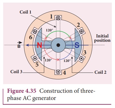
The initial position of
the field magnet is horizontal and field direction is perpendicular to the
plane of the coil 1. As it is seen in single phase AC generator, when field magnet
is rotated from that position in clockwise direction,
alternating emf ε1 in coil 1 begins a cycle from origin O. This is shown in Figure
4.36.![]()
![]()
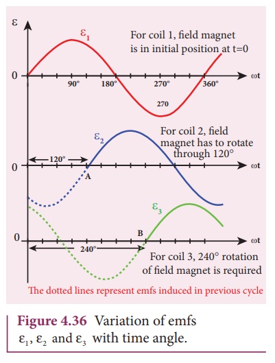
The corresponding cycle
for alternating emf ε2 in coil 2 starts at point A after field magnet has rotated through
120°. Therefore, the phase difference between ε1 and ε2 is 120°. Similarly, emf ε3 in coil 3 would begin its cycle at point B after 240° rotation of
field magnet from initial position. Thus these emfs produced in the three phase
AC generator have 120° phase difference between one another.
7. Advantages of three-phase alternator
Three-phase system has
many advantages over single-phase system. Let us see a few of them.
1) For a given
dimension of the generator, three-phase machine produces higher power output
than a single-phase machine.
2) For the same
capacity, three-phase alternator is smaller in size when compared to single
phase alternator.
3) Three-phase
transmission system is cheaper. A relatively thinner wire is sufficient for
transmission of three-phase power.
Related Topics