Chapter: 12th Physics : Electromagnetic Induction and Alternating Current
FaradayŌĆÖs Experiments on Electromagnetic Induction
FaradayŌĆÖs Experiments on Electromagnetic Induction
First Experiment
Consider a closed
circuit consisting of a coil C of insulated wire and a galvanometer G
as shown in Figure 4.2(a). The galvanometer does not indicate deflection as
there is no electric current in the circuit.
When a bar magnet is
inserted into the stationary coil, with its north pole facing the coil, there
is a momentary deflection in the galvanometer. This indicates that an electric
current is set up in the coil (Figure 4.2(b)). If the magnet is kept stationary
inside the coil, the galvanometer does not indicate deflection (Figure 4.2(c)).
The bar magnet is now
withdrawn from the coil, the galvanometer again gives a momentary deflection
but in the opposite direction. So the electric current flows in opposite
direction (Figure 4.2(d)). Now if the magnet is moved faster, it gives a larger
deflection due to a greater current in the circuit (Figure 4.2(e))
The bar magnet is
reversed i.e., the south pole now faces the coil. When the above experiment is
repeated, the deflections are opposite to that obtained in the case of north
pole (Figure 4.2(f)).
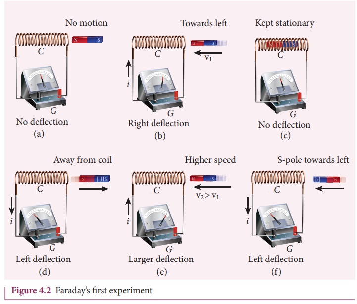
If the magnet is kept
stationary and the coil is moved towards or away from the coil, similar results
are obtained. It is concluded that whenever there is a relative motion between
the coil and the magnet, there is deflection in the galvanometer, indicating
the electric current setup in the coil.
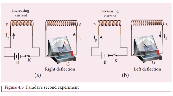
Second Experiment
Consider two closed
circuits as shown in Figure 4.3(a). The circuit consisting of a coil P,
a battery B and a key K is called as primary circuit while the
circuit with a coil S and a galvanometer G is known as secondary
circuit. The coils P and S are kept at rest in close proximity
with respect to one another.
If the primary circuit
is closed, electric current starts flowing in the primary circuit. At that
time, the galvanometer gives a momentary deflection (Figure 4.3(a)).
After that, when the
electric current reaches a certain steady value, no deflection is observed in
the galvanometer.
Likewise if the primary
circuit is broken, the electric current starts decreasing and there is again a
sudden deflection but in the opposite direction (Figure 4.3(b)). When the
electric current becomes zero, the galvanometer shows no deflection.
From the above
observations, it is concluded that whenever the electric current in the primary
circuit changes, the galvanometer shows a deflection.
FaradayŌĆÖs Law of Electromagnetic Induction
From the results of his
experiments, Faraday realized that
whenever the magnetic
flux linked with a closed coil changes, an emf (electromotive force) is induced
and hence an electric current flows in the circuit. This current is called an
induced current and the emf giving rise to such current is called an induced
emf. This phenomenon is known as electromagnetic induction.
Based on this idea,
FaradayŌĆÖs experiments are understood in the following way. In the first
experiment, when a bar magnet is placed close to a coil, some of the magnetic
field lines of the bar magnet pass through the coil i.e., the magnetic flux is
linked with the coil. When the bar magnet and the coil approach each other, the
magnetic flux linked with the coil increases. So this increase in magnetic flux
induces an emf and hence a transient
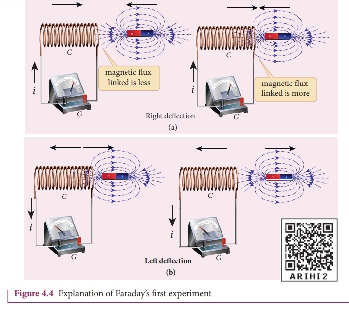
At the same time, when
they recede away from one another, the magnetic flux linked with the coil
decreases. The decrease in magnetic flux again induces an emf in opposite
direction and hence an electric current flows in opposite direction (Figure
4.4(b)). So there is deflection in the galvanometer when there is a relative motion between the coil and the
magnet.
In the second
experiment, when the primary coil P carries an electric current, a
magnetic field is established around it. The magnetic lines of this field pass
through itself and the neighbouring secondary coil S.
When the primary circuit
is open, no electric current flows in it and hence the magnetic flux linked
with the secondary coil is zero (Figure 4.5(a)).
However, when the
primary circuit is closed, the increasing current builds up a magnetic field
around the primary coil. Therefore, the magnetic flux linked with the secondary
coil increases. This increasing flux linked induces a transient electric
current in the secondary coil (Figure 4.5(b)). When the electric current in the
primary coil reaches a steady value, the magnetic flux linked with the
secondary coil does not change and the electric current in the secondary coil
will disappear.
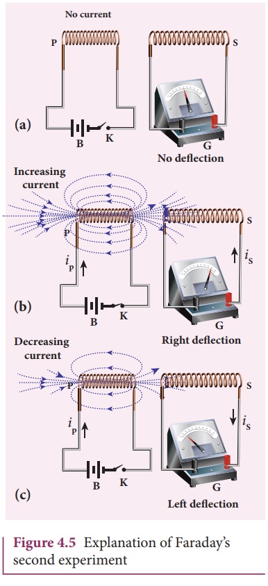
Similarly, when the
primary circuit is broken, the decreasing primary current induces an electric
current in the secondary coil, but in the opposite direction (Figure 4.5(c)).
So there is deflection in the galvanometer whenever there is a change in the
primary current.
The conclusions of
FaradayŌĆÖs experiments are stated as two laws.
First law
Whenever magnetic flux
linked with a closed circuit changes, an emf is induced in the circuit.
Second law
The magnitude of induced
emf in a closed circuit is equal to the time rate of change of magnetic flux
linked with the circuit.
If the magnetic flux
linked with the coil changes by d╬”B in a time dt, then
the induced emf is given by

The negative sign in the
above equation gives the direction of the induced current which will be dealt
with in the next section. If a coil consisting of N turns is tightly wound such
that each turn covers the same area, then the flux through each turn will be
the same. Then total emf induced in the coil is given by
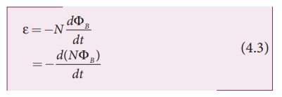
Here, N╬”B
is called flux linkage, defined as the product of number of turns N of
the coil and the magnetic flux linking each turn of the coil ╬”B.
EXAMPLE 4.3
A
cylindrical bar magnet is kept along the axis of a circular solenoid. If the
magnet is rotated about its axis, find out whether an electric current is
induced in the coil.
Solution
The
magnetic field of a cylindrical magnet is symmetrical about its axis. As the
magnet is rotated along the axis of the solenoid, there is no induced current
in the solenoid because the flux linked with the solenoid does not change due
to the rotation of the magnet.
EXAMPLE 4.4
A closed
coil of 40 turns and of area 200 cm2, is rotated in a magnetic field
of flux density 2 Wb m-2. It rotates from a position where its plane
makes an angle of 30┬║ with the
field to a position perpendicular to the field in a time 0.2 sec. Find the
magnitude of the emf induced in the coil due to its rotation.
Solution
N = 40 turns; B = 2 Wb m-2
A = 200 cm2 = 200 ┬┤ 10-4 m2;
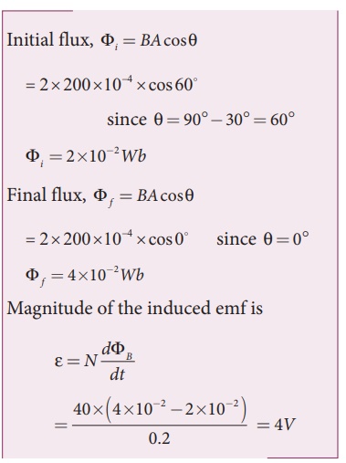
EXAMPLE 4.5
A
straight conducting wire is dropped horizontally from a certain height with its
length along east ŌĆō west direction. Will an emf be induced in it? Justify your
answer.
Solution
Yes! An
emf will be induced in the wire because it moves perpendicular to the
horizontal component of EarthŌĆÖs magnetic field.
Related Topics