Phasor and phasor diagram, Definition, Explanation, Formulas, Solved Example Problems | Alternating Current (AC) - RMS value of AC | 12th Physics : Electromagnetic Induction and Alternating Current
Chapter: 12th Physics : Electromagnetic Induction and Alternating Current
RMS value of AC
RMS value of AC
The term RMS refers to
time-varying sinusoidal currents and voltages and not used in DC systems.
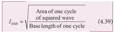
The root mean square
value of an alternating current is defined as the square root of the mean of
the squares of all currents over one cycle. It is denoted by IRMS . For alternating voltages, the RMS value is given by VRMS.
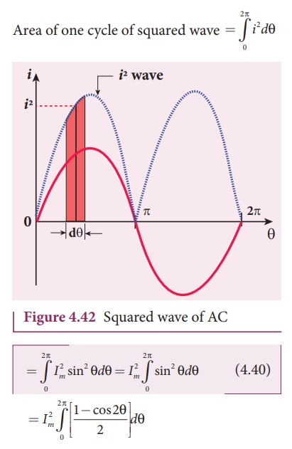
The alternating current
i = I m sin Žē t or i = Im sin╬Ė , is represented
graphically in Figure 4.42. The corresponding squared current wave is also
shown by the dotted lines.
The sum of the squares
of all currents over one cycle is given by the area of one cycle of squared
wave. Therefore,
An elementary area of
thickness d╬Ė is considered in the first half-cycle of the squared current wave
as shown in Figure 4.42. Let i2 be the mid-ordinate of the
element.
Area of the element = i 2d╬Ė
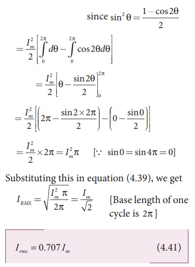
Thus we find that for a symmetrical sinusoidal current rms value of current is 70.7 % of its peak value.
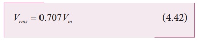
Similarly for alternating voltage, it can be shown that
EXAMPLE 4.18
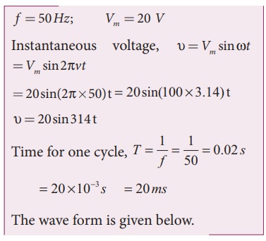
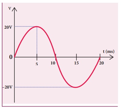
Write down the equation
for a sinusoidal voltage of 50 Hz and its peak value is 20 V. Draw the
corresponding voltage versus time graph.
Solution
EXAMPLE 4.19
The equation for an
alternating current is given by i =
77 sin 314t. Find the peak value,
frequency, time period and instantaneous value at t = 2 ms.
Solution
i = 77 sin 314t ; t = 2
ms = 2├Ś10-3 s
The general equation of
an alternating current is i = Im sin Žēt . On comparsion,
(i) Peak value, Im
= 77 A
(ii) Frequency, f = Žē/2ŽĆ = 314 / 2 ├Ś3.14 = 50 Hz
Time period, T = 1/f = 150 = 0 .02 s
(iv) At t = 2 m s,
Instantaneous value,
i = 77sin(314├Ś2├Ś10ŌłÆ3 )
i = 45.24 A
Phasor and phasor diagram
Phasor
A sinusoidal alternating
voltage (or current) can be represented by a vector which rotates about the
origin in anti-clockwise direction at a constant angular velocity Žē. Such a
rotating vector is called a phasor. A phasor is drawn in such a way that
┬Ę
the length of the line segment equals the peak value Vm
(or Im) of the alternating voltage (or current)
┬Ę
its angular velocity Žē is equal to the angular frequency of the
alternating voltage (or current)
┬Ę
the projection of phasor on any vertical axis gives the
instantaneous value of the alternating voltage (or current)
┬Ę
the angle between the phasor and the axis of reference (positive
x-axis) indicates the phase of the alternating voltage (or current).
The notion of phasors is
introduced to analyse phase relationship between voltage and current in
different AC circuits.
Phasor diagram
The diagram which shows
various phasors and their phase relations is called phasor diagram. Consider a
sinusoidal alternating voltage Žģ = Vm sin Žēt applied
to a circuit. This voltage can be represented by a phasor, namely ![]() as shown in Figure 4.43.
as shown in Figure 4.43.
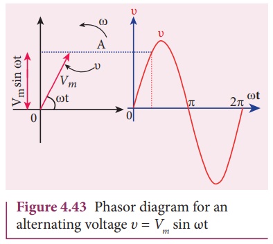
Here the length of ![]() equals the peak value (Vm), the angle it makes with x-axis
gives the phase (Žēt) of the applied voltage. Its projection on y-axis provides
the instantaneous value (Vm sin Žēt) at that instant.
equals the peak value (Vm), the angle it makes with x-axis
gives the phase (Žēt) of the applied voltage. Its projection on y-axis provides
the instantaneous value (Vm sin Žēt) at that instant.
When ![]() rotates about O with angular velocity Žē in anti-clockwise direction, the waveform of the voltage
is generated. For one full rotation of
rotates about O with angular velocity Žē in anti-clockwise direction, the waveform of the voltage
is generated. For one full rotation of ![]() , one cycle of
voltage is produced.
, one cycle of
voltage is produced.
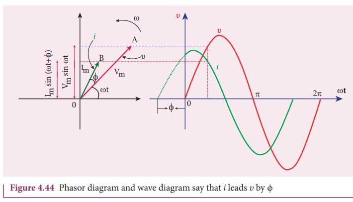
The alternating current
in the same circuit may be given by the relation iŌĆå=ŌĆåImsin
(Žēt + ŽĢ) which is represented by another phasor ![]() . Here ŽĢ is the phase angle between voltage and current. In this case, the
current leads the voltage by phase angle ŽĢ which is shown in Figure 4.44. If
the current lags behind the voltage, then we write i = Im
sin (Žēt - ŽĢ).
. Here ŽĢ is the phase angle between voltage and current. In this case, the
current leads the voltage by phase angle ŽĢ which is shown in Figure 4.44. If
the current lags behind the voltage, then we write i = Im
sin (Žēt - ŽĢ).
Related Topics