Chapter: 12th Physics : Electromagnetic Induction and Alternating Current
Methods of Producing Induced Emf
METHODS OF PRODUCING INDUCED EMF
Introduction
Electromotive force is
the characteristic of any energy source capable of driving electric charge
around a circuit. We have already learnt that it is not actually a force. It is
the work done in moving unit electric charge around the circuit. It is measured
in J C-1 or volt.
Some examples of energy
source which provide emf are electrochemical cells, thermoelectric devices,
solar cells and electrical generators. Of these, electrical generators are most
powerful machines. They are used for large scale power generation.
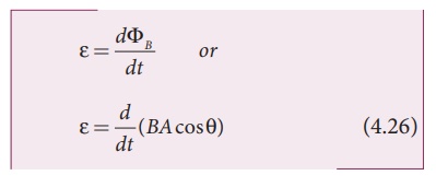
According to Faraday’s
law of electromagnetic induction, an emf is induced in a circuit when magnetic
flux linked with it changes. This emf is called induced emf. The magnitude of
the induced emf is given by
From the above equation,
it is clear that induced emf can be produced by changing magnetic flux in any
of the following ways.
i.
By changing the magnetic field B
ii.
By changing the area A of the coil and
iii.
By changing the relative orientation θ of the coil with magnetic
field
1. Induction of emf by changing the magnetic field
From Faraday’s
experiments on electromagnetic induction, it was discovered that an emf is
induced in a circuit on changing the magnetic flux of the field through it. The
change in flux is brought about by (i) relative motion between the circuit and
the magnet (First experiment) variation in current flowing through the nearby
coil (Second experiment).
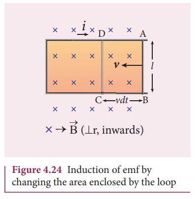
2. Induction of emf by changing the area of the coil
Consider a conducting
rod of length l moving with a velocity v towards left on a
rectangular metallic framework as shown in Figure 4.24. The whole arrangement
is placed in a uniform magnetic field ![]() whose magnetic lines
are perpendicularly directed into the plane of the paper.
whose magnetic lines
are perpendicularly directed into the plane of the paper.
As the rod moves from AB
to DC in a time dt, the area enclosed by the loop and hence the
magnetic flux through the loop decreases.
The change in magnetic
flux in time dt is
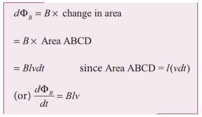
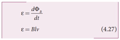
As a result of change in
flux, an emf is generated in the loop. The magnitude of the induced emf is
This emf is called motional
emf. The direction of induced current is found to be clockwise from
Fleming’s right hand rule.
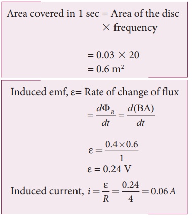
EXAMPLE 4.14
A circular metal of area
0.03 m2 rotates in a uniform magnetic field of 0.4 T. The axis of
rotation passes through the centre and perpendicular to its plane and is also
parallel to the field. If the disc completes 20 revolutions in one second and
the resistance of the disc is 4 Ω, calculate the induced emf between the axis
and the rim and induced current flowing in the disc.
Solution
A = 0.03 m2;
B = 0.4 T; f = 20 rps; R = 4 Ω
3. Induction of emf by changing relative orientation of the coil with the magnetic field
Consider a rectangular
coil of N turns kept in a uniform magnetic field ![]() as
shown in Figure 4.25(a). The coil rotates in anti-clockwise direction with an
angular velocity about an axis, perpendicular to the field.
as
shown in Figure 4.25(a). The coil rotates in anti-clockwise direction with an
angular velocity about an axis, perpendicular to the field.
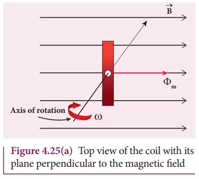
At time = 0, the plane
of the coil is perpendicular to the field and the flux linked with the coil has
its maximum value Фm = BA (where A is the area of the
coil).
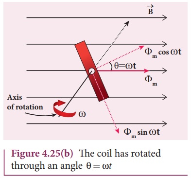
In a time t
seconds, the coil is rotated through an angle θ (= ωt) in anti–clockwise
direction. In this position, the flux linked is Фm cos ωt, a
component of Фm normal to the plane of the coil (Figure 4.25(b)).
The component parallel to the plane (Фm sin ωt) has no role in
electromagnetic induction.
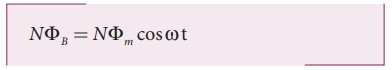
Therefore, the flux
linkage at this deflected position is
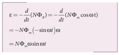
According to Faraday’s
law, the emf induced at that instant is
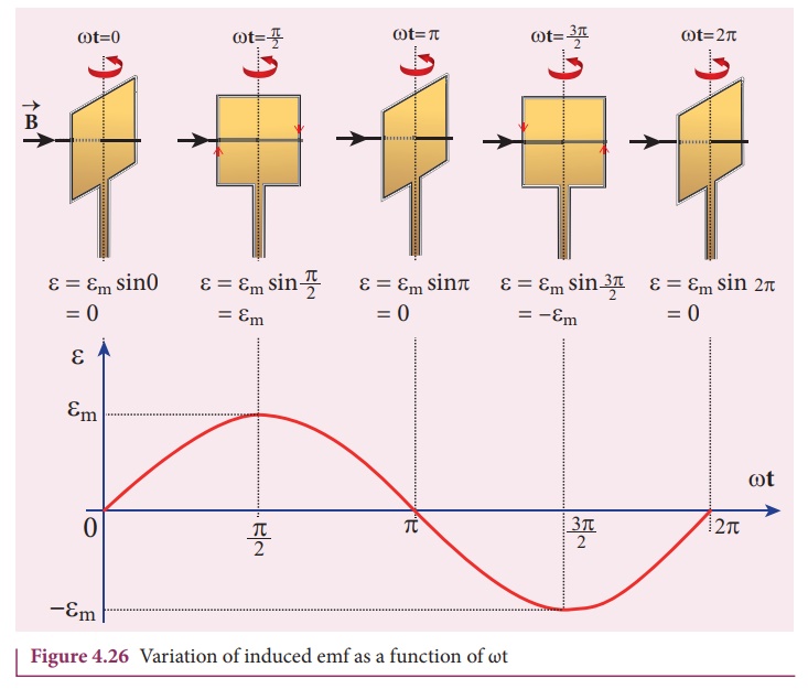
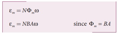
When the coil is rotated
through 90o from initial position, sin ωt = 1. Then the maximum value of
induced emf is
Therefore, the value of
induced emf at that instant is then given by
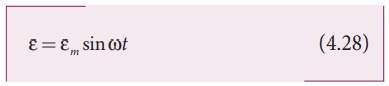
It is seen that the
induced emf varies as sine function of the time angle ωt. The graph
between induced emf and time angle for one rotation of coil will be a sine
curve (Figure 4.26) and the emf varying in this manner is called sinusoidal emf
or alternating emf.
If this alternating
voltage is given to a closed circuit, a sinusoidally varying current flows in
it. This current is called alternating current and is given by
where Im
is the maximum value of induced current.
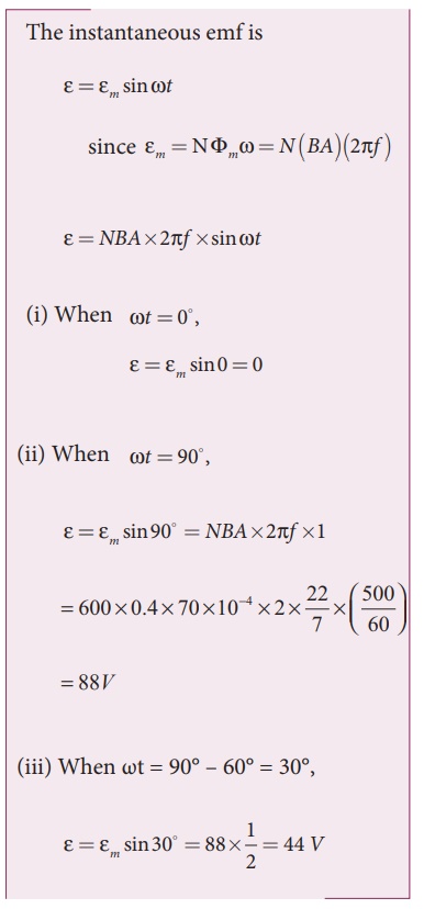
EXAMPLE 4.15
A rectangular coil of
area 70 cm2 having 600 turns rotates about an axis perpendicular to a magnetic
field of 0.4 Wb m-2. If the coil completes 500 revolutions in a
minute, calculate the instantaneous emf when the plane of the coil is (i)
perpendicular to the field (ii) parallel to the field and (iii) inclined at 60o
with the field.
Solution
A = 70 ´ 10-4m2;
N = 600 turns
B = 0.4 Wbm-2;
f = 500 rpm
Related Topics