Chapter: 12th Physics : Magnetism and Magnetic Effects of Electric Current
Torque Acting on a Bar Magnet in Uniform Magnetic Field
TORQUE ACTING ON A BAR MAGNET IN UNIFORM MAGNETIC FIELD
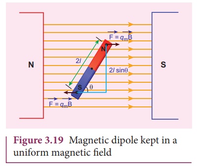
Consider a magnet of
length 2l of pole strength qm kept in a uniform magnetic
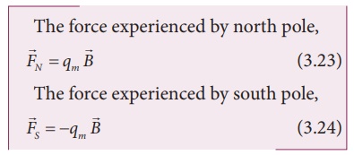
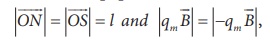
field B as shown in Figure 3.19. Each pole experiences a force of
magnitude qmB but acts in opposite direction. Therefore, the net
force exerted on the magnet is zero, so that there is no translatory motion.
These two forces constitute a couple (about midpoint of bar magnet) which will
rotate and try to align in the direction of the magnetic field ![]() .
.
Adding equations (3.23)
and (3.24), we get the net force acting on the dipole as
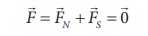
This implies, that the
net force acting on the dipole is zero, but forms a couple which tends to
rotate the bar magnet clockwise (here) in order to align it along ![]() .
.
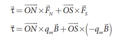
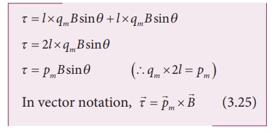
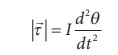
The moment of force or
torque experienced by north and south pole about point O is
By using right hand cork screw rule, we conclude that the total torque is pointing into the paper. Since the magnitudes
the magnitude of total torque about point O
EXAMPLE 3.7
Show the time period of
oscillation when a bar magnet is kept in a uniform magnetic field is 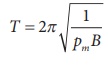 in second, where I represents moment Pm of inertia of the bar magnet, pm is the
magnetic moment and is the magnetic field.
in second, where I represents moment Pm of inertia of the bar magnet, pm is the
magnetic moment and is the magnetic field.
Solution
The magnitude of
deflecting torque (the torque which makes the object rotate) acting on the bar
magnet which will tend to align the bar magnet parallel to the direction of the
uniform magnetic field ![]() is
is
The magnitude of
restoring torque acting on the bar magnet can be written as
Under equilibrium
conditions, both magnitude of deflecting torque and restoring torque will be
equal but act in the opposite directions, which means
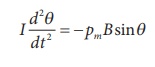
The negative sign implies that both
are in opposite directions. The above equation can be written as
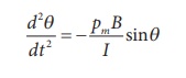
This is non-linear second order
homogeneous differential equation. In order to make it linear, we use small
angle approximation as we did in XI volume II (Unit 10 ŌĆō oscillations, Refer
section 10.4.4) i.e., sin, we get
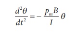
This linear second order homogeneous
differential equation is a Simple Harmonic differential equation. Therefore,
Comparing with Simple Harmonic
Motion (SHM) differential equation
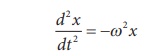
where Žē is the angular frequency of
the oscillation.
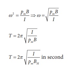
where, BH is the
horizontal component of EarthŌĆÖs magnetic field.
1. Potential energy of a bar magnet in a uniform magnetic field
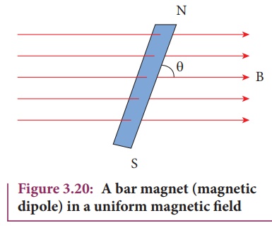
When a bar magnet
(magnetic dipole) of dipole moment ![]() m is held at an
angle ╬Ė with the direction of a uniform magnetic field
m is held at an
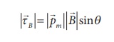
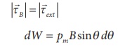
angle ╬Ė with the direction of a uniform magnetic field ![]() , as
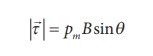
shown in Figure 3.20 the magnitude of the torque acting on the dipole is
, as
shown in Figure 3.20 the magnitude of the torque acting on the dipole is
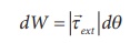
If the dipole is rotated
through a very small angular displacement d╬Ė against the torque ŽäB
at constant angular velocity, then the work done by external torque (![]() ) for this small angular displacement is given by
) for this small angular displacement is given by
The bar magnet has to be
moved at constant angular velocity, which implies that
Total work done in
rotating the dipole from ╬Ė═┤ to ╬Ė is
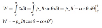
This work done is stored
as potential energy in bar magnet at an angle ╬Ė when it is rotated from ╬Ė═┤
to ╬Ė and it can be written as
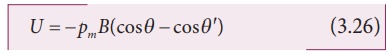
In fact, the equation
(3.26) gives the difference in potential energy between the angular positions ╬Ė═┤
and ╬Ė. We can choose the reference point ╬Ė═┤ = 90o, so that second term
in the equation becomes zero and the equation (3.26) can be written as
The potential energy stored
in a bar magnet in a uniform magnetic field is given by
Case 1
(i) If ╬Ė
= 0┬║, then
U =
ŌłÆ pm B (cos0 ┬║ ) = ŌłÆ pm B
(ii) If ╬Ė
= 180 ┬║, then
U= ŌłÆ pm B (cos180 ┬║) = pm B
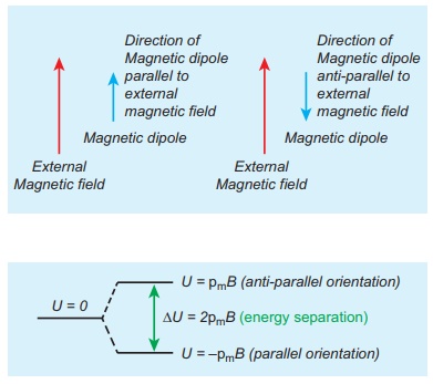
We can infer from the
above two results, the potential energy of the bar magnet is minimum when it is
aligned along the external magnetic field and maximum when the bar magnet is
aligned anti-parallel to external magnetic field.
EXAMPLE 3.8
Consider a magnetic
dipole which on switching ON external magnetic field orient only in two
possible ways i.e., one along the direction of the magnetic field (parallel to
the field) and another anti-parallel to magnetic field. Compute the energy for
the possible orientation. Sketch the graph.
Solution
Let ![]() m be the
dipole and before switching ON the external magnetic field, there is no
orientation. Therefore, the energy U = 0.
m be the
dipole and before switching ON the external magnetic field, there is no
orientation. Therefore, the energy U = 0.
As soon as external
magnetic field is switched ON, the magnetic dipole orient parallel (╬Ė = 0┬║) to
the magnetic field with energy,
Uparallel = Uminimum
= ŌłÆ pm B cos0
Uparallel = ŌłÆ
pm B
since cos 0┬║ = 1
Otherwise, the magnetic
dipole orients anti-parallel (╬Ė = 180┬║) to the magnetic field with energy,
UantiŌłÆ parallel
= U maximum =ŌłÆ pmB cos180
ŌćÆU
antiŌłÆparallel = pmB
since cos 180┬║ = -1
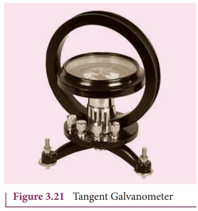
2. Tangent law and Tangent Galvanometer
Tangent Galvanometer
(Figure 3.21) is a device used to measure very small currents. It is a moving
magnet type galvanometer. Its working is based on tangent law.
Tangent law
When a magnetic needle
or magnet is freely suspended in two mutually perpendicular uniform magnetic
fields, it will come to rest in the direction of the resultant of the two
fields.
Let B be the magnetic
field produced by passing current through the coil of the tangent Galvanometer
and BH be the horizontal component of earthŌĆÖs magnetic field. Under
the action of two magnetic fields, the needle comes to rest making angle ╬Ė with
BH, such that
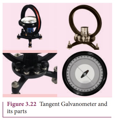
Construction
Tangent Galvanometer
(TG) consists of copper coil wounded on a non-magnetic circular frame. The
frame is made up of brass or wood which is mounted vertically on a horizontal
base table (turn table) with three levelling screws as shown in Figure 3.22.
The TG is provided with two or more coils of different number of turns. Most of the
equipment we use in laboratory consists of 2 turns, 5 turns and 50 turns which
are of different thickness and are used for measuring currents of different
strengths.
At the center of turn
table, a small upright projection is seen on which compass box (also known as
magnetometre box) is placed. Compass box consists of a small magnetic needle
which is pivoted at the center, such that arrangement shows the center of both
magnetic needle and circular coil exactly coincide. A thin aluminium pointer is
attached to the magnetic needle normally and moves over circular scale. The
circular scale is divided into four quadrants and graduated in degrees which
are used to measure the deflection of aluminium pointer on a circular degree
scale. In order to avoid parallax error in measurement, a mirror is placed
below the aluminium pointer.
Precautions
1. All the nearby magnets
and magnetic materials are kept away from the instrument.
2. Using spirit level,
the levelling screws at the base are adjustedso that the small magnetic needle
is exactly horizontal and also coil (mounted on the frame) is exactly vertical.
3. The plane of the coil is kept parallel to the small magnetic needle by rotating the coil about its vertical axis. So, the coil remains in magnetic meridian.
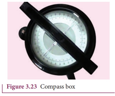
4. The compass box (as shown in Figure 3.23) is rotated such that the pointer reads 0┬║ ŌĆō 0 ┬║
Theory
The circuit connection
for Tangent Galvanometer (TG) experiment is shown in Figure 3.24. When no
current is passed through the coil, the small magnetic needle lies along
horizontal component of EarthŌĆÖs magnetic field. When the circuit is switched
ON, the electric current will pass through the circular coil and produce
magnetic field. The magnetic field produced due to the circulatory electric
current is discussed (in section 3.8.3). Now there are two fields which
are acting mutually perpendicular to each other. They are:
(1) the magnetic field
(B) due to the electric current in the coil acting normal to the plane of the
coil.
(2) the horizontal
component of EarthŌĆÖs magnetic field (BH)
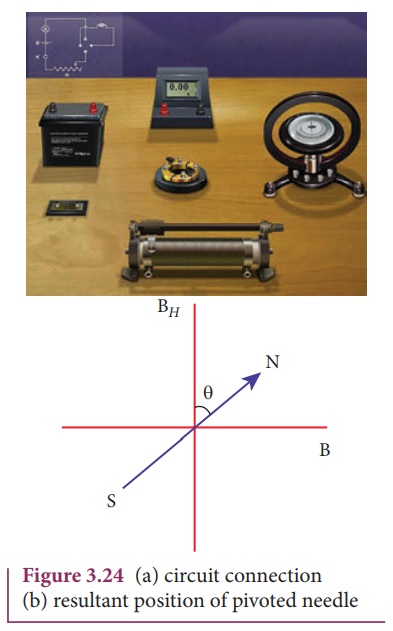
Because of these crossed
fields, the pivoted magnetic needle deflects through an angle ╬Ė. From tangent
law (equation 3.29),
B = BH tan ╬Ė
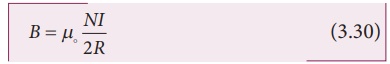
When an electric current
is passed through a circular coil of radius R having N turns, the magnitude of
magnetic field at the center is
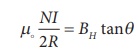
From equation (3.29)
and equation (3.30), we get
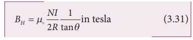
The horizontal component
of EarthŌĆÖs magnetic field can be determined as
EXAMPLE 3.9
A coil of a tangent
galvanometer of diametre 0.24 m has 100 turns. If the horizontal component of
EarthŌĆÖs magnetic field is 25 ├Ś 10-6 T then, calculate the current
which gives a deflection of 60┬║.
Solution
The diameter of the coil
is 0.24 m.
Therefore, radius of the
coil is 0.12 m.
Number of turns is 100
turns. EarthŌĆÖs magnetic field is 25 x 10-6 T
Deflection is
╬Ė=60 ┬║ Ō¤╣ tan 60 ┬║ = ŌłÜ3 = 1.732
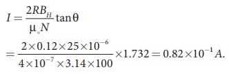
I = 0.082 A
Related Topics