Definition, explanation, Formula, Application, Solved Example Problems - Lorentz Force | 12th Physics : Magnetism and Magnetic Effects of Electric Current
Chapter: 12th Physics : Magnetism and Magnetic Effects of Electric Current
Lorentz Force
LORENTZ FORCE
When an electric charge
q is kept at rest in a magnetic field, no force acts on it. At the same time,
if the charge moves in the magnetic field, it experiences a force. This force
is different from Coulomb force, studied in unit 1. This force is known as
magnetic force. It is given by the equation

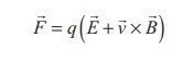
In general, if the
charge is moving in both the electric and magnetic fields, the total force
experienced by the charge is given by 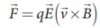 . It is known as Lorentz
force.
. It is known as Lorentz
force.
1. Force on a moving charge in a magnetic field
When an electric charge
q is moving with velocity ![]() in the magnetic field
in the magnetic field ![]() ,
it experiences a force, called magnetic force
,
it experiences a force, called magnetic force ![]() .
After careful experiments, Lorentz deduced the force experienced by a
moving charge in the magnetic field
.
After careful experiments, Lorentz deduced the force experienced by a
moving charge in the magnetic field ![]()
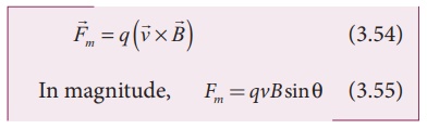
The equations (3.54) and
(3.55) imply
1. ![]() is directly proportional to the magnetic field
is directly proportional to the magnetic field ![]()
2. ![]() is directly proportional to the velocity
is directly proportional to the velocity ![]()
3. ![]() is directly proportional to sine of the angle between the velocity and magnetic
field
is directly proportional to sine of the angle between the velocity and magnetic
field
4. ![]() is directly proportional to the magnitude of the charge q
is directly proportional to the magnitude of the charge q
5. The direction of ![]() is always perpendicular to
is always perpendicular to ![]() and
and ![]() as
as ![]() is the cross product of
is the cross product of ![]() and
and ![]()
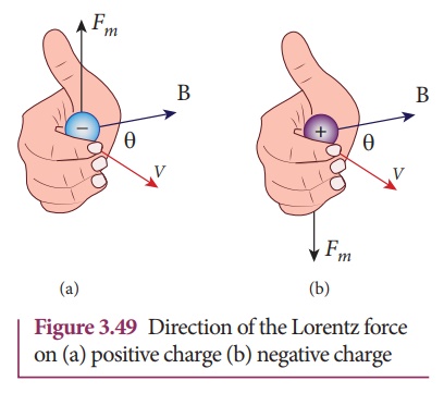
6. The direction of ![]() on negative charge is opposite to the direction of
on negative charge is opposite to the direction of ![]() on positive charge provided other factors are identical as shown Figure 3.49
on positive charge provided other factors are identical as shown Figure 3.49
7. If velocity ![]() of the charge q is along magnetic field
of the charge q is along magnetic field ![]() then,
then, ![]() is zero
is zero
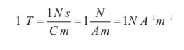
Definition of tesla
The strength of the
magnetic field is one tesla if unit charge moving in it with unit velocity
experiences unit force.
EXAMPLE 3.20
A particle of charge q
moves with along positive y - direction invelocity ![]() a magnetic
field
a magnetic
field ![]() . Compute the Lorentz force experienced by the particle (a)
when magnetic field is along positive y-direction (b) when magnetic field
points in positive z - direction (c) when magnetic field is in zy - plane and
making an angle θ with velocity of the particle. Mark the direction of magnetic
force in each case.
. Compute the Lorentz force experienced by the particle (a)
when magnetic field is along positive y-direction (b) when magnetic field
points in positive z - direction (c) when magnetic field is in zy - plane and
making an angle θ with velocity of the particle. Mark the direction of magnetic
force in each case.
Solution
Velocity of the particle
is 
(a) Magnetic field is
along positive y - direction, this
implies, 
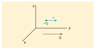
From Lorentz force, 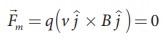
So, no force acts on the
particle when it moves along the direction of magnetic field.
(b) Magnetic field
points in positive z - direction, this implies, 
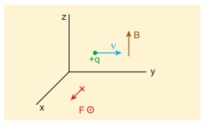
From Lorentz force,
Therefore, the magnitude
of the Lorentz force is qvB and direction is along positive x - direction.
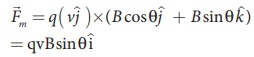
(c) Magnetic field is in
zy - plane and making an angle θ with the velocity of the particle, which
implies 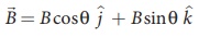
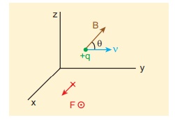
From Lorentz force,
EXAMPLE 3.21
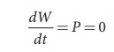
Compute the work done
and power delivered by the Lorentz force on the particle of charge q moving
with velocity ![]() . Calculate the angle between Lorentz force and
velocity of the charged particle and also interpret the result.
. Calculate the angle between Lorentz force and
velocity of the charged particle and also interpret the result.
Solution
For a charged particle
moving on a magnetic field,

The work done by the
magnetic field is
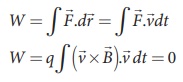
Since ![]() is perpendicular to
is perpendicular to ![]() and hence
and hence  This means that Lorentz force do no work on the
particle. From work kinetic energy theorem, (Refer section 4th chapter, XI th
standard Volume I)
This means that Lorentz force do no work on the
particle. From work kinetic energy theorem, (Refer section 4th chapter, XI th
standard Volume I)
Since,  and
and ![]() are perpendicular to
each other. The angle between Lorentz force and velocity of the charged
particle is 90º. Thus Lorentz force changes the direction of the velocity but
not the magnitude of the velocity. Hence Lorentz force does no work and also
does not alter kinetic energy of the particle.
are perpendicular to
each other. The angle between Lorentz force and velocity of the charged
particle is 90º. Thus Lorentz force changes the direction of the velocity but
not the magnitude of the velocity. Hence Lorentz force does no work and also
does not alter kinetic energy of the particle.
2. Motion of a charged particle in a uniform magnetic field
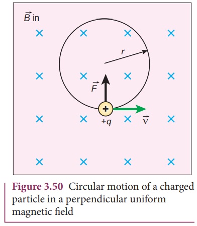
Consider a charged
particle of charge q having mass m enters into a region of uniform magnetic
field ![]() with velocity
with velocity ![]() such that velocity is
perpendicular to the magnetic field. As soon as the particle enters into the
field, Lorentz force acts on it in a direction perpendicular to both magnetic
field
such that velocity is
perpendicular to the magnetic field. As soon as the particle enters into the
field, Lorentz force acts on it in a direction perpendicular to both magnetic
field ![]() and velocity
and velocity ![]() .
.
As a result, the charged
particle moves in a circular orbit as shown in Figure 3.50.
The Lorentz force on the
charged particle is given by
Since Lorentz force
alone acts on the particle, the magnitude of the net force on the particle is
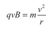
This Lorentz force acts
as centripetal force for the particle to execute circular motion. Therefore,
The radius of the
circular path is
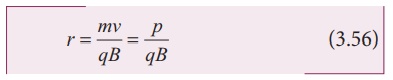
where p = mv is the
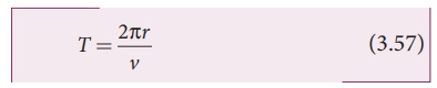
magnitude of the linear momentum of the particle. Let T be the time taken by
the particle to finish one complete circular motion, then
Hence substituting
(3.56) in (3.57), we get
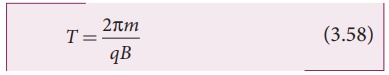
Equation (3.58) is
called the cyclotron period. The reciprocal of time period is the
frequency f, which is
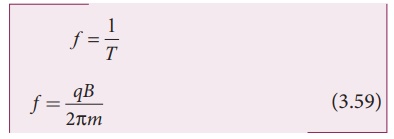
In terms of angular
frequency ω,
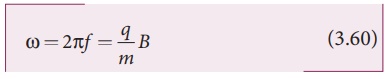
Equations (3.59) and
(3.60) are called as cyclotron frequency or gyro-frequency.
From equations (3.58),
(3.59) and (3.60), we infer that time period and frequency depend only on
charge-to-mass ratio (specific charge) but not velocity or the radius of the
circular path.
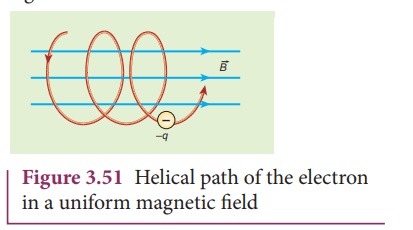
If a charged particle
moves in a region of uniform magnetic field such that its velocity is not
perpendicular to the magnetic field, then the velocity of the particle is split
up into two components; one component is parallel to the field while the other
perpendicular to the field. The component of velocity parallel to field remains
unchanged and the component perpendicular to field keeps changing due to the
Lorentz force. Hence the path of the particle is not a circle; it is a helix
around the field lines as shown in Figure 3.51.
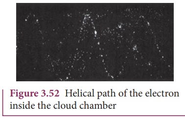
For an example, the
helical path of an electron when it moves in a magnetic field is shown in
Figure 3.52. Inside the particle detector called cloud chamber, the path is
made visible by the condensation of water droplets.
EXAMPLE 3.22
An electron moving
perpendicular to a uniform magnetic field 0.500 T undergoes circular motion of
radius 2.80 mm. What is the speed of electron?
Solution
Charge of an electron q
= -1.60 × 10⁻¹⁹ C
⟹
|q| = 1.60 ×10⁻¹⁹ C
Magnitude of magnetic
field B = 0.500 T
Mass of the electron, m
= 9.11 × 10⁻³¹ kg
Radius of the orbit, r =
2.50 mm = 2.50 × 10⁻³ m
Velocity of the
electron, v = |q| rB/m
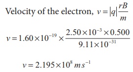
v = 2.195 ×10⁸ m s−1
EXAMPLE 3.23
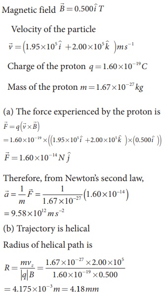
A proton moves in a
uniform magnetic field of strength 0.500 T magnetic field is directed along the
x-axis. At initial time, t = 0 s, the proton has velocity 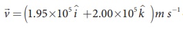 . Find
(a) At initial time,
what is the acceleration of the proton.
(b) Is the path circular
or helical?. If helical, calculate the radius of helical trajectory and also
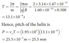
calculate the pitch of the helix (Note: Pitch of the helix is the distance
travelled along the helix axis per revolution).
Solution
Pitch of the helix is the distance
travelled along x-axis in a time T, which is P = vx T
But time,
The proton experiences appreciable
acceleration in the magnetic field, hence the pitch of the helix is almost six
times greater than the radius of the helix.
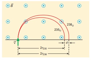
EXAMPLE 3.24
Two singly ionized
isotopes of uranium 23592U and 23892U
(isotopes have same atomic number but different mass number) are sent with
velocity 1.00 × 10⁵ m s-1 into a magnetic field of
strength 0.500 T normally. Compute the distance between the two isotopes after
they complete a semi-circle. Also compute the time taken by each isotope to
complete one semi-circular path. (Given: masses of the isotopes: m235
= 3.90 x 10⁻²⁵ kg and m238 = 3.95 x 10⁻²⁵ kg)
Solution
Since isotopes are singly ionized,
they have equal charge which is equal to the charge of an electron, q = - 1.6 ×
10-19 C. Mass of uranium 23592U and 23892U
are 3.90 × 10⁻²⁵ kg and 3.95 × 10⁻²⁵ kg respectively.
Magnetic field applied, B = 0.500 T. Velocity of the electron is 1.00 × 10⁵
m s-1, then
(a) the radius of the path of 23592U
is r235
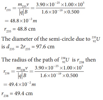
The diameter of the semi-circle due
to 23892U is d238 = 2r238 = 98.8 cm
Therefore the separation distance
between the isotopes is Δd = d238 − d235 = 1.2cm
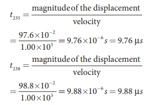
(b) The time taken by each isotope
to complete one semi-circular path are
Note that even though
the difference between mass of two isotopes are very small, this arrangement
helps us to convert this small difference into an easily measurable distance of
separation. This arrangement is known as mass spectrometer. A mass spectrometer
is used in many areas in sciences, especially in medicine, in space science, in
geology etc. For example, in medicine, anaesthesiologists use it to measure the
respiratory gases and biologist use it to determine the reaction mechanisms in
photosynthesis.
3. Motion of a charged particle under crossed electric and magnetic field (velocity selector)
Consider an electric
charge q of mass m which enters into a region of uniform magnetic field ![]() with velocity
with velocity ![]() such that velocity is not perpendicular to the
magnetic field. Then the path of the particle is a helix. The Lorentz force on
the charged particle moving in a uniform magnetic field can be balanced by
Coulomb force by proper arrangement of electric and magnetic fields.
such that velocity is not perpendicular to the
magnetic field. Then the path of the particle is a helix. The Lorentz force on
the charged particle moving in a uniform magnetic field can be balanced by
Coulomb force by proper arrangement of electric and magnetic fields.
The Coulomb force acts
along the direction of electric field (for a positive charge q) whereas the
Lorentz force is perpendicular to the direction of magnetic field. Therefore in
order to balance these forces, both electric and magnetic fields must be
perpendicular to each other. Such an arrangement of perpendicular electric and
magnetic fields are known as cross fields.
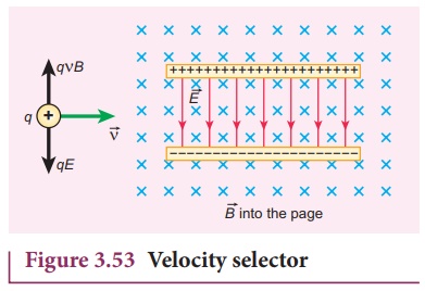
For illustration, consider an experimental
arrangement as shown in Figure 3.53. In the region of space between parallel
plates of a capacitor (which produces uniform electric field), uniform magnetic
field is maintained perpendicular to the direction of electric field. Suppose a
charged particle enters this space from the left side as shown, the net force
on the particle is
For a positive charge,
the electric force on the charge acts in downward direction whereas the Lorentz
force acts upwards. When these two forces balance one another, then
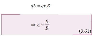
This means, for a given
magnitude of ![]() - field and
- field and ![]() - field, the forces
act only for the particle moving with particular speed v0 = E/B . This speed is
independent of mass and charge.
- field, the forces
act only for the particle moving with particular speed v0 = E/B . This speed is
independent of mass and charge.
If the charge enters
into the crossed fields with velocity v, other than vo, it results
in any of the following possibilities (Table 3.4).
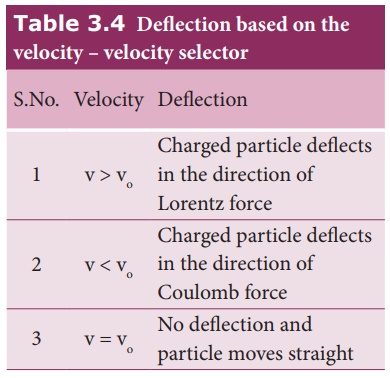
So by proper choice of electric and
magnetic fields, the particle with particular speed can be selected. Such an
arrangement of fields is called a velocity
selector.
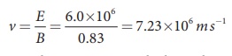
EXAMPLE 3.25
Let E be the electric
field of magnitude 6.0 × 10⁶ N C-1 and B be the magnetic
field magnitude 0.83 T. Suppose an electron is accelerated with a potential of
200 V, will it show zero deflection?. If not, at what potential will it show
zero deflection.
Solution:
Electric field, E = 6.0
× 106 N C-1 and magnetic field, B = 0.83 T.
Then
When an electron goes
with this velocity, it shows null deflection. Since the accelerating potential
is 200 V, the electron acquires kinetic energy because of this accelerating
potential. Hence,
Since the mass of the
electron, m = 9 .1×10−31 kg and charge of an electron, |q| = e = 1.6
×10−19 C. The velocity due to accelerating potential 200 V
Since the speed v200
> v, the electron is deflected towards direction of Lorentz force. So, in
order to have null deflection, the potential, we have to supply is
V =148 65 V
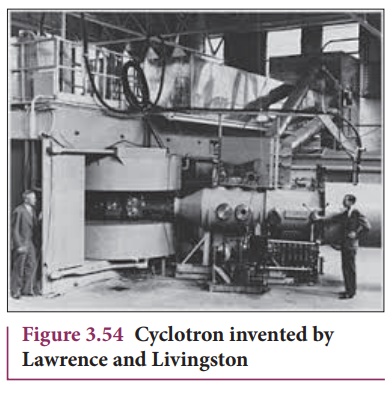
4. Cyclotron
Cyclotron (Figure 3.54)
is a device used to accelerate the charged particles to gain large kinetic
energy. It is also called as high energy accelerator. It was invented by
Lawrence and Livingston in 1934.
Principle
When a charged particle
moves normal to the magnetic field, it experiences magnetic Lorentz force.
Construction
The schematic diagram of
a cyclotron is shown in Figure 3.55. The particles are allowed to move in
between two semi-circular metal containers called Dees (hollow D - shaped
objects). Dees are enclosed in an evacuated chamber and it is kept in a region
with uniform magnetic field controlled by an electromagnet. The direction of
magnetic field is normal to the plane of the Dees. The two Dees are kept
separated with a gap and the source S (which ejects the particle to be
accelerated) is placed at the center in the gap between the Dees. Dees are
connected to high frequency alternating potential difference.
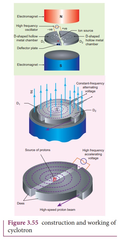
Working
Let us assume that the
ion ejected from source S is positively charged. As soon as ion is ejected, it
is accelerated towards a Dee (say, Dee – 1) which has negative potential at
that time. Since the magnetic field is normal to the plane of the Dees, the ion
undergoes circular path. After one semi-circular path in Dee-1, the ion reaches
the gap between Dees. At this time, the polarities of the Dees are reversed so
that the ion is now accelerated towards Dee-2 with a greater velocity. For this
circular motion, the centripetal force of the charged particle q is provided by
Lorentz force.
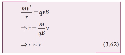
From the equation
(3.62), the increase in velocity increases the radius of circular path. This
process continues and hence the particle undergoes spiral path of increasing
radius. Once it reaches near the edge, it is taken out with the help of
deflector plate and allowed to hit the target T.
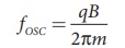
Very important condition
in cyclotron operation is the resonance condition. It happens when the
frequency f at which the positive ion circulates in the magnetic field
must be equal to the constant frequency of the electrical oscillator fosc
From equation (3.59), we
have
The time period of oscillation
is

The kinetic energy of
the charged particle is

Limitations of cyclotron
a) the speed of the ion is
limited
b) electron cannot be
accelerated
c) uncharged particles
cannot be accelerated
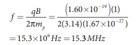
EXAMPLE 3.26
Suppose a cyclotron is
operated to accelerate protons with a magnetic field of strength 1 T. Calculate
the frequency in which the electric field between two Dees could be reversed.
Solution
Magnetic field B = 1 T
Mass of the proton, mp
= 1.67 ×10⁻²⁷ kg
Charge of the proton, q
= 1.60 ×10⁻¹⁹ C
5. Force on a current carrying conductor placed in a magnetic field
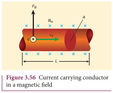
When a current carrying
conductor is placed in a magnetic field, the force experienced by the wire is
equal to the sum of Lorentz forces on the individual charge carriers in the
wire. Consider a small segment of wire of length dl, with
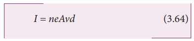
cross-sectional area A and current I as shown in Figure 3.56. The free
electrons drift opposite to the direction of current. So the relation between
current I and magnitude of drift velocity vd (Refer Unit 2) is
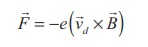
If the wire is kept in a
magnetic field ![]() , then average force experienced by the
charge (here, electron) in the wire is
, then average force experienced by the
charge (here, electron) in the wire is
Let n be the number of
free electrons per unit volume, therefore
where N is the number of
free electrons in the small element of volume V = A dl.
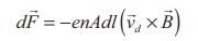
Hence Lorentz force on
the wire of length dl is the product of the number of the electrons
(N = nA dl) and
the force acting on an electron.
The length dl is
along the length of the wire and hence the current element in the wire is 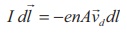
Therefore the force on
the wire is

The force in a straight
current carrying conducting wire of length l placed in a uniform
magnetic field is

In magnitude,
F = BIl sinθ
(a) If the conductor is
placed along the direction of the magnetic field, the angle between them is θ =
0º. Hence, the force experienced by the conductor is zero.
(b) If the conductor is
placed perpendicular to the magnetic field, the angle between them is θ =90º
Hence, the force experienced by the conductor is maximum, which is F = BIl.
Fleming’s left hand rule (mnemonic)
When a current carrying
conductor is placed in a magnetic field, the direction of the force experienced
by it is given by Fleming’s Left Hand Rule (FLHR) as shown in Figure 3.57.
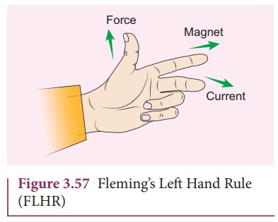
Stretch forefinger, the
middle finger and the thumb of the left hand such that they are in mutually
perpendicular directions. If forefinger points the direction of magnetic field,
the middle finger points the direction of the electric current, then thumb will
point the direction of the force experienced by the conductor.
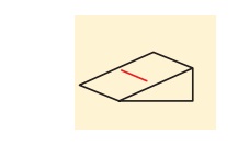
EXAMPLE 3.27
A metallic rod of linear
density is 0.25 kg m-1 is lying horizontally on a smooth inclined plane which
makes an angle of 45º with the horizontal. The rod is not allowed to slide down
by flowing a current through it when a magnetic field of strength 0.25 T is
acting on it in the vertical direction. Calculate the electric current flowing
in the rod to keep it stationary.
Solution
The linear density of
the rod i.e., mass per unit length of the rod is 0.25 kg m-1
⇒
m/l
= 0.25 kg m−1
Let I be the current
flowing in the metallic rod. The direction of electric current is into the
paper. The direction of magnetic force IBl is given by Fleming’s left hand
rule.
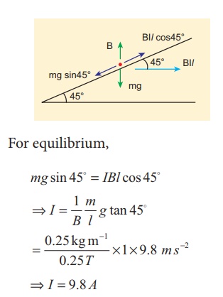
For equilibrium,
mg sin 45º = IBl cos 45 º
⇒ I = I/B m/l g tan 45 º
⇒ I = 9.8 A
So, we need to supply current of 9.8 A to keep the metallic rod stationary.
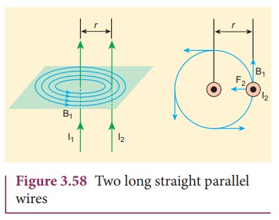
6. Force between two long parallel current carrying conductors
Two long straight
parallel current carrying conductors separated by a distance r are kept in air
as shown in Figure 3.58. Let I1 and I2 be the electric
currents passing through the conductors A and B in same direction (i.e. along z
- direction) respectively. The net magnetic field at a distance r due to
current I1 in conductor A is
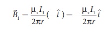
From thumb rule, the
direction of magnetic field is perpendicular to the plane of the paper and
inwards (arrow into the page ⊗) i.e. along negative i
^ direction.
Let us consider a small
elemental length dl in conductor B at which the magnetic field B1
is present. From equation 3.65, Lorentz force on the element dl
of conductor B is
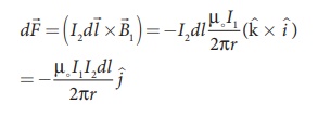
Therefore the force on dl
of the wire B is directed towards the wire W1. So the length dl
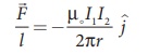
is attracted towards the conductor A. The force per unit length of the
conductor B due to the wire conductor A is
In the same manner, we
compute the magnitude of net magnetic induction due to current I2
(in conductor A) at a distance r in the elemental length dl of conductor
A is
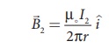
From the thumb rule,
direction of magnetic field is perpendicular to the plane of the paper and
outwards (arrow out of the page ʘ) i.e., along positive i ^ direction.
Hence, the magnetic
force at element dl of the wire is W1 is
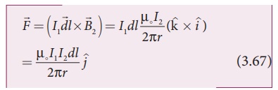
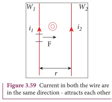
Therefore the force on dl
of conductor A is directed towards the conductor B. So the length dl is
attracted towards the conductor B as shown in Figure (3.59).
The force per unit
length of the conductor A due to the conductor B is
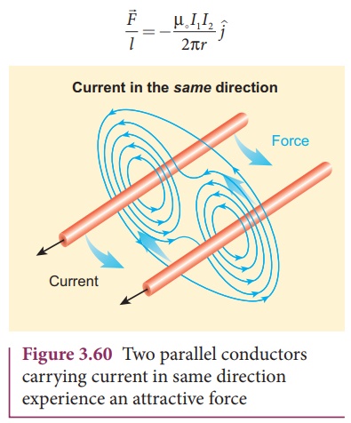
Thus the force
experienced by two parallel current carrying conductors is attractive if the
direction of electric current passing through them is same as shown in Figure
3.60.
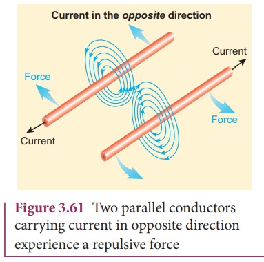
Thus the force
experienced by two parallel current carrying conductors is repulsive if they
carry current in the opposite directions as shown in Figure 3.61.
Definition of ampère
One ampère is defined as
that current when it is passed through each of the two infinitely long parallel
straight conductors kept at a distance of one meter apart in vacuum causes each
conductor to experience a force of 2 × 10⁻⁷ newton per meter length of conductor.
Related Topics