Definition, explanation, Solved Example Problems - Biot - Savart Law | 12th Physics : Magnetism and Magnetic Effects of Electric Current
Chapter: 12th Physics : Magnetism and Magnetic Effects of Electric Current
Biot - Savart Law
BIOT - SAVART LAW
Soon after the OerstedŌĆÖs
discovery, both Jean-Baptiste Biot and Felix Savart in 1819 did quantitative
experiments on the force experienced by a magnet kept near current carrying
wire and arrived at a mathematical expression that gives the magnetic field at
some point in space in terms of the current that produces the magnetic field.
This is true for any shape of the conductor.
1. Definition and explanation of Biot- Savart law
Biot and Savart
experimentally observed that the magnitude of magnetic field d![]() at a point P (Figure 3.37) at a distance r from the small elemental length
taken on a conductor carrying current varies
at a point P (Figure 3.37) at a distance r from the small elemental length
taken on a conductor carrying current varies
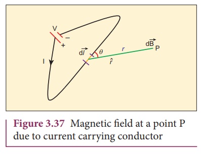
i.directly as the strength of the current I
ii.directly as the
magnitude of the length element ![]()
iii.directly as the sine of
the angle (say,╬Ė) between ![]() and r ^ .
and r ^ .
iv.inversely as the square
of the distance between the point P and length element ![]() .
.
This is expressed as
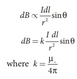
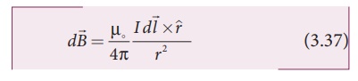
in SI units and k = 1 in CGS units. In vector notation,
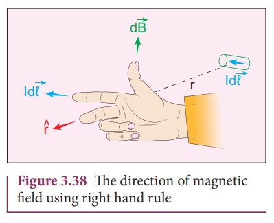
Here vector d![]() is perpendicular to both I
is perpendicular to both I ![]() (pointing the direction of
current flow) and the unit vector r ^ directed from
(pointing the direction of
current flow) and the unit vector r ^ directed from ![]() toward
point P (Figure 3.38).
toward
point P (Figure 3.38).
The equation (3.37) is
used to compute the magnetic field only due to a small elemental length dl
of the conductor. The net magnetic field at P due to the conductor is obtained
from principle of superposition by considering the contribution from all
current elements I ![]() . Hence integrating equation (3.37), we
get
. Hence integrating equation (3.37), we
get
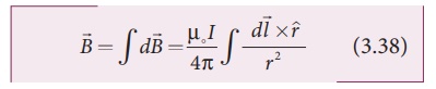
where the integral is
taken over the entire current distribution.
Cases
1. If the point P lies on
the conductor, then ╬Ė = 0┬║. Therefore, d ![]() is zero.
is zero.
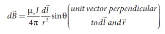
2. If the point lies
perpendicular to the conductor, then ╬Ė = 90┬║. Therefore, d ![]() is maximum and is given by
is maximum and is given by  where
where ![]() is the unit vector perpendicular to both I
is the unit vector perpendicular to both I ![]() and
and ![]() .
.
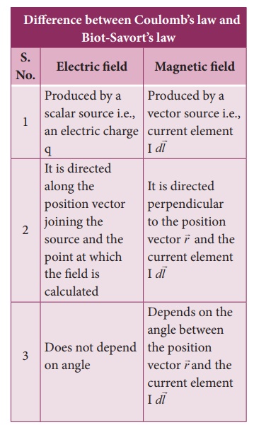
Similarities between
CoulombŌĆÖs law and Biot-SavortŌĆÖs law
Electric and magnetic
fields
┬Ę
obey inverse square law, so they are long range fields.
┬Ę
obey the principle of superposition and are linear with respect to
source. In magnitude,

Note that the exponent
of charge q (source) and exponent of electric field E is unity. Similarly, the
exponent of current element Idl (source) and exponent of magnetic field
B is unity. In other words, electric field ![]() is proportional
only to charge (source) and not on higher powers of charge ( q2 , q3
, etc). Similarly, magnetic
field
is proportional
only to charge (source) and not on higher powers of charge ( q2 , q3
, etc). Similarly, magnetic
field ![]() is proportional to current element I
is proportional to current element I![]() (source) and not on square or cube or higher powers of current element. The
cause and effect have linear relationship.
(source) and not on square or cube or higher powers of current element. The
cause and effect have linear relationship.
2. Magnetic field due to long straight conductor carrying current
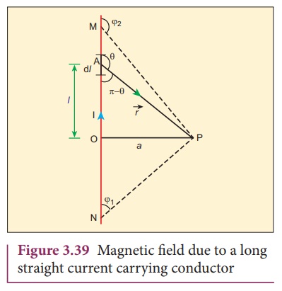
Consider a long straight
wire NM with current I flowing from N to M as shown in Figure 3.39. Let P be
the point at a distance a from point O. Consider an element of length dl
of the wire at a distance l from point O and ![]() be the
vector joining the element dl with the point P. Let ╬Ė be the angle
between
be the
vector joining the element dl with the point P. Let ╬Ė be the angle
between ![]() and
and ![]() . Then, the magnetic
field at P due to the element is
. Then, the magnetic
field at P due to the element is
The direction of the
field is perpendicular to the plane of the paper and going into it. This can be
determined by taking the cross product between two vectors ![]() and
and ![]() (let it be n^ ). The net magnetic field can be
determined by integrating equation (3.38) with proper limits.
(let it be n^ ). The net magnetic field can be
determined by integrating equation (3.38) with proper limits.
From the Figure 3.39, in
a right angle triangle PAO,
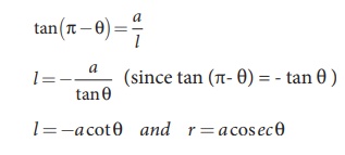
Differentiating,
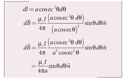
This is the magnetic
field at a point P due to the current in small elemental length. Note that we
have expressed the magnetic field OP in terms of angular coordinate i.e. ╬Ė.
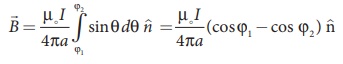
Therefore, the net magnetic field at the point P which can be obtained by
integrating d![]() by varying the angle from ╬Ė = Žå1 to ╬Ė
= Žå2 is
by varying the angle from ╬Ė = Žå1 to ╬Ė
= Žå2 is
For a an infinitely long straight
wire, ŽĢ1 = 0 and ŽĢ2 = ŽĆ, the magnetic field is
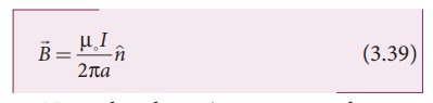
Note that here n ^ represents the unit
vector from the point O to P.
EXAMPLE 3.15
Calculate the magnetic
field at a point P which is perpendicular bisector to current carrying straight
wire as shown in figure.
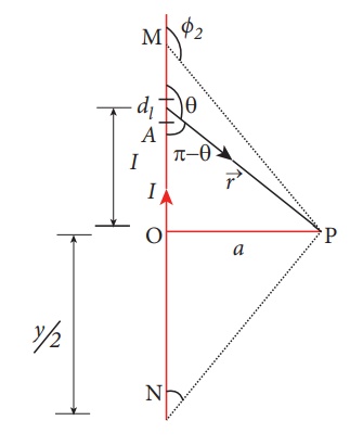
Solution
Let the length MN = y
and the point P is on its perpendicular bisector. Let O be the point on the
conductor as shown in figure.
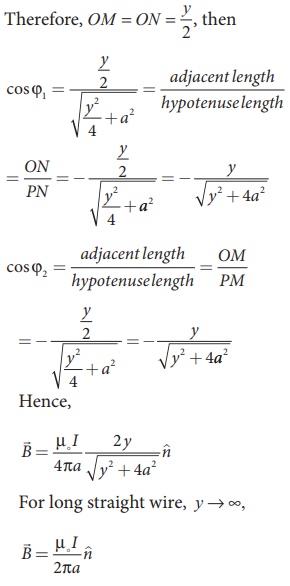
The result obtained is same as we obtained in equation (3.39).
EXAMPLE 3.16
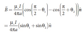
Show that for a straight
conductor, the magnetic field
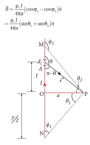
Solution:
In a right angle
triangle OPN, let the angle ŌłĀ OPN = ╬Ė1
which implies, ŽĢ1 = ŽĆ /2 ŌłÆ ╬Ė1
and also in a right angle triangle OPM, ŌłĀOPM = ╬Ė2
which implies, ŽĢ2 = ŽĆ/2 + ╬Ė2
Hence,
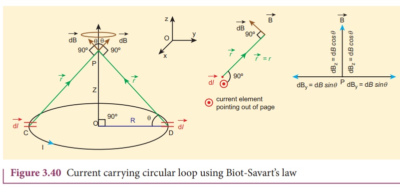
3. Magnetic field produced along the axis of the current carrying circular coil
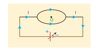
Consider a current
carrying circular loop of radius R and let I be the current flowing through the
wire in the direction as shown in Figure 3.40. The magnetic field at a point P
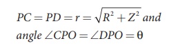
on the axis of the circular coil at a distance z from its center of the
coil O. It is computed by taking two diametrically opposite line
elements of the coil each of length ![]() at C and D. Let
at C and D. Let ![]() be the vector joining the current element (I
be the vector joining the current element (I ![]() ) at
C to the point P.
) at
C to the point P.
According to Biot-SavartŌĆÖs
law, the magnetic field at P due to the current element I![]() is
is
The magnitude of
magnetic field due to current element I ![]() at C and D
are equal because of equal distance from the coil. The magnetic field d
at C and D
are equal because of equal distance from the coil. The magnetic field d ![]() due to each current element I
due to each current element I![]() is resolved into two
components; dB sin ╬Ė along y - direction and dB cos ╬Ė along z - direction.
Horizontal components of each current element cancels out while the vertical
components (dB cos ╬Ė
is resolved into two
components; dB sin ╬Ė along y - direction and dB cos ╬Ė along z - direction.
Horizontal components of each current element cancels out while the vertical
components (dB cos ╬Ė ![]() ) alone contribute to total magnetic field at
the point P.
) alone contribute to total magnetic field at
the point P.
If we integrate ![]() around the loop, d
around the loop, d ![]() sweeps out a cone as shown in Figure 3.40,
then the net magnetic field
sweeps out a cone as shown in Figure 3.40,
then the net magnetic field ![]() at point P is
at point P is
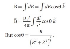
using Pythagorous theorem r2= R2+Z2
and integrating line element from 0 to 2ŽĆR, we get
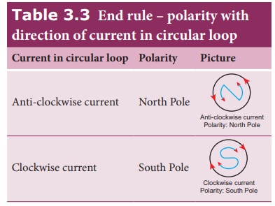
Note that the magnetic
field ![]() points along the direction from the point O to P. Suppose if
the current flows in clockwise direction, then magnetic field points in the
direction from the point P to O.
points along the direction from the point O to P. Suppose if
the current flows in clockwise direction, then magnetic field points in the
direction from the point P to O.
EXAMPLE 3.17
What is the magnetic
field at the center of the loop shown in figure?
Solution
The magnetic field due
to current in the upper hemisphere and lower hemisphere of the circular coil
are equal in magnitude but opposite in direction. Hence, the net magnetic field
at the center of the loop (at point O) is zero ![]() .
.
4. Current loop as a magnetic dipole
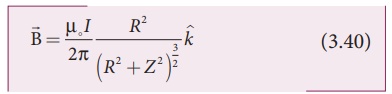
The magnetic field from
the centre of a circular loop of radius R along the axis is given by
At larger distance Z >> R, therefore R2
+ Z2 Ōēł Z2 , we
have
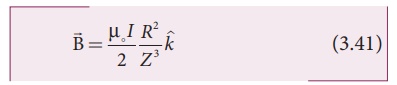
Let A be the area of the
circular loop A = ŽĆ R2. So rewriting the equation (3.41) in terms of
area of the loop, we have
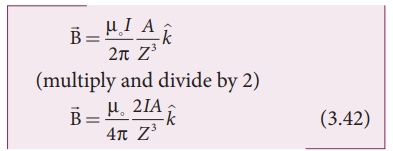
Comparing equation (3.42) with equation (3.14) dimensionally, we get
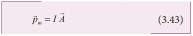
pm = I
A
where pm is
called magnetic dipole moment. In vector notation,
This implies that a
current carrying circular loop behaves as a magnetic dipole of magnetic moment ![]() m . So, the magnetic dipole moment of any current
loop is equal to the product of the current and area of the loop.
m . So, the magnetic dipole moment of any current
loop is equal to the product of the current and area of the loop.
Right hand thumb rule
In order to determine
the direction of magnetic moment, we use right hand thumb rule (mnemonic) which
states that
If we curl the fingers
of right hand in the direction of current in the loop, then the stretched thumb
gives the direction of the magnetic moment associated with the loop.
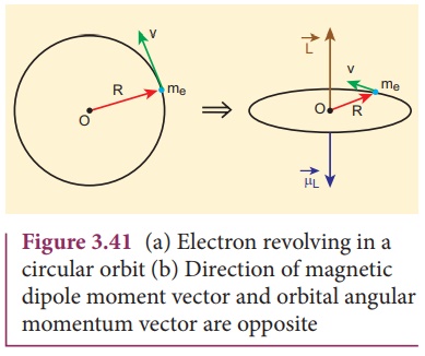
5. Magnetic dipole moment of revolving electron
Suppose an electron
undergoes circular motion around the nucleus as shown in Figure 3.41. The
circulating electron in a loop is like current in a circular loop (since flow
of charge is current). The magnetic dipole moment due to current carrying
circular loop is
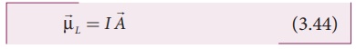
In magnitude,
┬ĄL = I A
If T is the time period
of an electron, the current due to circular motion of the electron is
where ŌłÆe is the
charge of an electron. If R is the radius of the circular orbit and v is the
velocity of the the velocity of the electron in the circular orbit, then
Using equation (3.45)
and equation (3.46) in equation (3.44), we get
where A = ŽĆR2 is the area of the circular loop. By definition, angular momentum of the electron about O is
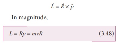
Using equation (3.47)
and equation (3.48), we get
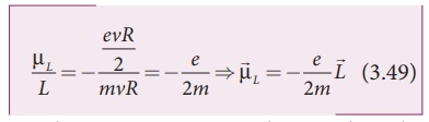
The negative sign
indicates that the magnetic moment and angular momentum are in opposite
direction.
In magnitude,
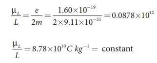
The ratio ┬ĄL/L is a
constant and also known as gyro-magnetic ratio (e/2m). It must be noted that the gyro-magnetic ratio is a constant of
proportionality which connects angular momentum of the electron and the
magnetic moment of the electron.
According to NeilŌĆÖs Bohr
quantization rule, the angular momentum of an electron moving in a stationary
orbit is quantized, which means,
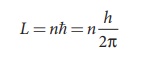
where, h is the PlanckŌĆÖs
constant (h = 6.63 x 10⁻³⁴ J s ) and number n takes natural numbers
(i.e., n = 1,2,3,....). Hence,
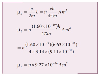
The minimum magnetic
moment can be obtained by substituting n = 1,
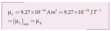
where, ┬ĄB
=eh/4ŽĆm= 9.27 ├Ś10ŌłÆ24 Am2 is called Bohr magneton. This is a convenient unit with which one can
measure atomic magnetic moments.
Note: Bohr quantization
rule will be discussed in unit 8 of second volume
Related Topics