Chapter: 11th Physics : UNIT 7 : Properties of Matter
BernoulliŌĆÖs theorem and its applications
BernoulliŌĆÖs theorem and its applications
In 1738, the Swiss scientist Daniel Bernoulli developed a relationship for the flow of fluid through a pipe of varying cross section. He proposed a theorem for the streamline flow of a liquid based on the law of conservation of energy.
BernoulliŌĆÖs theorem
![]()
![]() According to BernoulliŌĆÖs theorem, the sum of pressure energy, kinetic energy, and potential energy per unit mass of an incompressible, non-viscous fluid in a streamlined flow remains a constant. Mathematically,
According to BernoulliŌĆÖs theorem, the sum of pressure energy, kinetic energy, and potential energy per unit mass of an incompressible, non-viscous fluid in a streamlined flow remains a constant. Mathematically,

This is known as BernoulliŌĆÖs equation.
Proof:
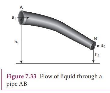
Let us consider a flow of liquid through a pipe AB as shown in Figure 7.33. Let V be the volume of the liquid when it enters A in a time t which is equal to the volume of the liquid leaving B in the same time. Let aA, vA and PA be the area of cross section of the tube, velocity of the liquid and pressure exerted by the liquid at A respectively.
Let the force exerted by the liquid at A is
FA = PAaA
Distance travelled by the liquid in time t is
d = vA t
Therefore, the work done is
W = FAd = PAaAvA t
But aAvAt = aAd =V, volume of the liquid entering at A.
Thus, the work done is the pressure energy (at A),ŌĆā
W = FAd = PAV
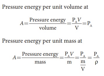
Since m is the mass of the liquid entering at A in a given time, therefore, pressure energy of the liquid at A is

Potential energy of the liquid at A,
PEA = mg hA,
Due to the flow of liquid, the kinetic energy of the liquid at A,

Therefore, the total energy due to the flow of liquid at A, EA = EPA + KEA + PEA

Similarly, let aB, vB, and PB be the area of cross section of the tube, velocity of the liquid, and pressure exerted by the liquid at B. Calculating the total energy at EB, we get

From the law of conservation of energy,
EA = EB
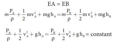
Thus, the above equation can be written as

The above equation is the consequence of the conservation of energy which is true until there is no loss of energy due to friction. But in practice, some energy is lost due to friction. This arises due to the fact that in a fluid flow, the layers flowing with different velocities exert frictional forces on each other. This loss of energy is generally converted into heat energy. Therefore, BernoulliŌĆÖs relation is strictly valid for fluids with zero viscosity or non-viscous liquids. Notice that when the liquid flows through a horizontal pipe, then h = 0

Applications of BernoulliŌĆÖs Theorem
(a) Blowing off roofs during wind storm
In olden days, the roofs of the huts or houses were designed with a slope as shown in Figure.7.34. One important scientific reason is that as per the BernoulliŌĆÖs principle, it will be safeguarded except roof during storm or cyclone.
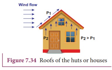
During cyclonic condition, the roof is blown off without damaging the other parts of the house. In accordance with the BernoulliŌĆÖs principle, the high wind blowing over the roof creates a low-pressure P1. The pressure under the roof P2 is greater. Therefore, this pressure difference (P2ŌĆōP1) creates an up thrust and the roof is blown off.
(b) Aerofoil lift
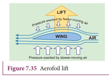
The wings of an airplane (aerofoil) are so designed that its upper surface is more curved than the lower surface and the front edge is broader than the real edge. As the aircraft moves, the air moves faster above the aerofoil than at the bottom as shown in Figure 7.35.
According to BernoulliŌĆÖs Principle, the pressure of air below is greater than above, which creates an upthrust called the dynamic lift to the aircraft.
(c) Bunsen burner
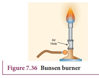
In this, the gas comes out of the nozzle with high velocity, hence the pressure in the stem decreases. So outside air reaches into the burner through an air vent and the mixture of air and gas gives a blue flame as shown in Figure 7.36.
(d) Venturimeter
This device is used to measure the rate of flow (or say flow speed) of the incompressible fluid flowing through a pipe. It works on the principle of BernoulliŌĆÖs theorem. It consists of two wider tubes A and A' (with cross sectional area A) connected by a narrow tube B (with cross sectional area a). A manometer in the form of U-tube is also attached between the wide and narrow tubes as shown in Figure7.37. The manometer contains a liquid of density ŌĆśŽümŌĆÖ.
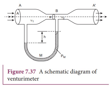
Let P1 be the pressure of the fluid at the wider region of the tube A. Let us assume that the fluid of density ŌĆśŽüŌĆÖ flows from the pipe with speed ŌĆśv1ŌĆÖ and into the narrow region, its speed increases to ŌĆśv2ŌĆÖ. According to the BernoulliŌĆÖs equation, this increase in speed is accompanied by a decrease in the fluid pressure P2 at the narrow region of the tube B. Therefore, the pressure difference between the tubes A and B is noted by measuring the height difference (╬öP = P1ŌłÆP2) between the surfaces of the manometer liquid.
From the equation of continuity, we can say that Av1 = a v2 which means that

Using BernoulliŌĆÖs equation,

From the above equation, the pressure difference

Thus, the speed of flow of fluid at the wide end of the tube A

The volume of the liquid flowing out per second is

(e) Other applications
This BernoulliŌĆÖs concept is mainly used in the design of carburetor of automobiles, filter pumps, atomizers, and sprayers.
For example, the carburetor has a very fine channel called nozzle through which the air is allowed to flow in larger speed. In this case, the pressure is lowered at the narrow neck and in turn, the required fuel or petrol is sucked into the chamber so as to provide the correct mixture of air and fuel necessary for ignition process.
Related Topics