Chapter: Modern Analytical Chemistry: Electrochemical Methods of Analysis
Classification of Electrochemical Methods
Classification of Electrochemical Methods
Although there are only three principal sources
for the analytical signal—potential,
current, and charge—a wide variety
of experimental designs
are possible;. The simplest division
is be- tween bulk methods, which measure properties of the whole solution, and interfa-
cial methods, in which the signal is a function
of phenomena occurring
at the inter- face between an electrode and the solution in contact with the electrode. The measurement of a solution’s conductivity, which is proportional to the total
con- centration of dissolved ions, is one example of a bulk electrochemical method.
A determination of pH using a pH electrode is one example
of an interfacial electro-
chemical method. Only interfacial electrochemical methods receive further
consid- eration in this text.
Interfacial Electrochemical Methods
The diversity of interfacial electrochemical methods is evident
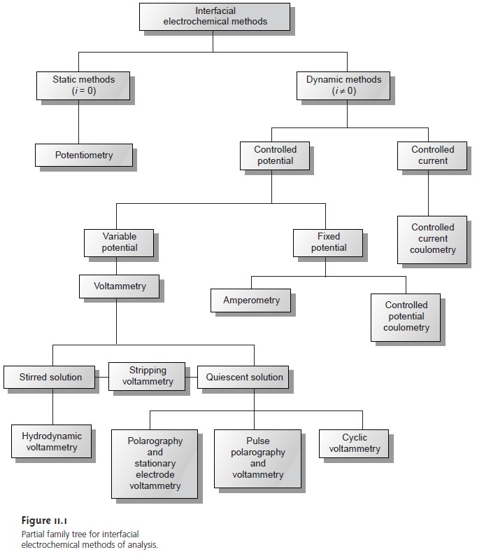
from the partial family tree shown in Figure
11.1. At the first level, interfacial electrochemical
methods are divided
into static methods
and dynamic methods.
In static methods no current passes between
the electrodes, and the concentrations of species in the
electrochemical cell remain unchanged, or static. Potentiometry, in which the po- tential of an electrochemical cell is measured
under static conditions, is one of the
most important quantitative electrochemical methods.

The largest division of interfacial electrochemical methods is the
group of dy- namic methods, in which
current flows and
concentrations change as the result
of a redox reaction.
Dynamic methods are further subdivided by whether we choose to control the current or the potential. In controlled-current coulometry, we completely oxidize
or reduce the analyte by passing a fixed
current through the
analytical solution. Controlled-potential methods
are subdivided further into controlled-potential coulometry and amperometry, in which a constant potential is applied
during the analysis,
and voltammetry, in which
the potential is systematically varied.
Controlling and Measuring Current and Potential
Electrochemical measurements are made in an electrochemical
cell, consisting of two or more electrodes and associated electronics for controlling and measuring the current and potential. In this section
the basic components of electrochemical in- strumentation
are introduced. Specific experimental
designs are considered in greater detail in the sections that follow.
The simplest electrochemical cell uses two electrodes. The potential of one of the electrodes is sensitive to the analyte’s concentration and is called the working, or indicator electrode. The second electrode, which is called the counter electrode, serves to complete the electric circuit and provides a reference potential against which the working electrode’s potential is measured. Ideally the counter electrode’s potential remains constant so that any change in the overall cell potential is attrib- uted to the working electrode. In a dynamic method, where the passage of current changes the concentration of species in the electrochemical cell, the potential of the counter electrode may change over time. This problem is eliminated by replacing the counter electrode with two electrodes: a reference electrode, through which no current flows and whose potential remains constant; and an auxiliary electrode that completes the electric circuit and through which current is allowed to flow.
Although many different electrochemical methods of analysis are
possible (Fig- ure 11.1)
there are only three basic
experimental designs: (1) measuring the potential
under static conditions of no current flow;
(2) measuring the
potential while con- trolling the current; and (3) measuring the current while controlling the potential.
Each of these experimental designs,
however, is based
on Ohm’s law that
a current, i, passing through
an electric circuit
of resistance, R, generates a potential, E; thus
E = iR
Each of these
experimental designs also uses a different type of instrument. To aid in understanding how they control
and measure current
and potential, these
in- struments are described as if they
were operated manually. To do so the analyst observes a change in current or potential and manually adjusts
the instrument’s set- tings to maintain the
desired experimental conditions. It is important to understand that modern electrochemical instruments provide an automated, electronic means of controlling and measuring current
and potential. They do so by using
very differ- ent electronic circuitry than that
shown here.
Potentiometers
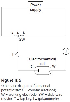
Measuring the potential of an electrochemical cell under condi- tions of zero current is accomplished using a potentiometer. A schematic diagram of a manual potentiometer is shown in Figure 11.2.

The current in the upper
half of the circuit is

where EPS is the power
supply’s potential, and
Rab is
the resistance between
points a and b of the slide-wire resistor. In a similar
manner, the current
in the lower half of the circuit is

where Ecell is the potential difference between the working electrode and the counter electrode, and Rcb is the resistance between the points
c
and b of the
slide-wire resis- tor. When

no current flows through the galvanometer and the cell potential
is given by

To make a measurement the tap key is pressed
momentarily, and the current is noted
at the galvanometer. If a nonzero current
is registered, then the slide
wire is adjusted and
the current remeasured. This process is continued until
the gal- vanometer
registers a current of zero. Using the tap key minimizes
the total amount of current allowed
to flow through the cell. Provided that the total cur-
rent is negligible, the change
in the analyte’s concentration is insignificant. For example, a current of 10–9 A
drawn for 1 s consumes
only about 10–14 mol of analyte. Modern potentiometers use operational amplifiers to create a high- impedance voltmeter capable of measuring potentials while drawing currents
of less than 10–9 A.
Galvanostats
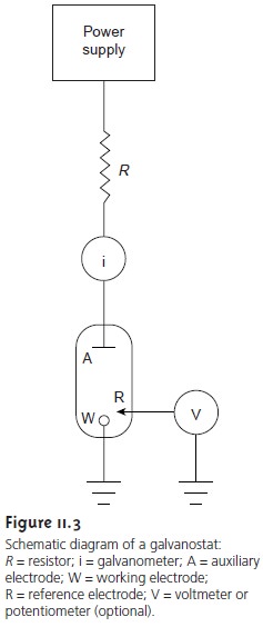
A galvanostat is
used for dynamic
methods, such as constant-current
coulometry, in which it is necessary to control the current flowing
through an elec- trochemical cell. A schematic diagram of a manual constant-current galvanostat is shown in Figure 11.3.
If the resistance, R, of the galvanostat is significantly larger than the resistance of the electrochemical cell, and the
applied voltage from
the power supply is much greater
than the cell potential, then the current
between the auxiliary and working electrodes is equal to


The potential of the working
electrode, which changes
as the composition of the electrochemical cell changes, is monitored by including a reference electrode and a high-impedance potentiometer.
Potentiostats
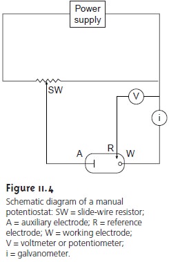
A potentiostat is
used for dynamic
methods when it is necessary to control the potential
of the working electrode. Figure 11.4 shows a schematic
dia- gram for a manual potentiostat that can be used to maintain a constant cell poten-
tial. The potential of the
working electrode is monitored by a reference electrode connected to the working electrode through a high-impedance potentiometer. The
desired potential is achieved by adjusting the slide-wire resistor connected to
the auxiliary electrode. If the working
electrode’s potential begins
to drift from the de- sired value, then the slide-wire resistor
is manually readjusted, returning the poten- tial to its initial
value. The current
flowing between the auxiliary and working elec- trodes is measured with
a galvanostat. Modern
potentiostats include waveform generators allowing
a time-dependent potential
profile, such as a series of potential pulses, to be applied
to the working electrode.

Related Topics