Chapter: Modern Analytical Chemistry: Electrochemical Methods of Analysis
Potentiometric Measurements - Potentiometric Methods of Analysis
Potentiometric Measurements
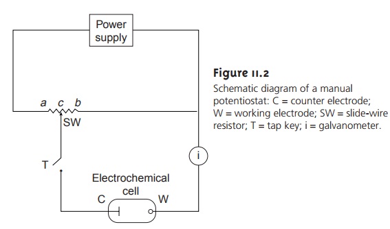
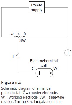
Potentiometric measurements are made using
a potentiometer to determine the dif-
ference in potential between a working or, indicator, electrode
and a counter elec- trode (see Figure 11.2).
Since no significant current flows in potentiometry, the role
of the counter electrode is reduced to that of supplying a reference potential; thus, the counter electrode
is usually called the reference
electrode. In this section we in-
troduce the conventions used in describing potentiometric electrochemical cells and the
relationship between the measured potential and concentration.
Potentiometric Electrochemical Cells
A schematic diagram
of a typical potentio-
metric electrochemical cell is shown in Figure 11.5. Note that the electrochemical cell is divided into two half-cells, each containing an electrode immersed
in a solu- tion containing ions whose concentrations determine the electrode’s potential. This
separation of electrodes is necessary
to prevent the redox reaction
from occurring spontaneously on the surface
of one of the electrodes, short-circuiting the electro- chemical cell and making the measurement of cell potential
impossible. A salt bridge containing an inert
electrolyte, such as KCl, connects
the two half-cells. The ends of the
salt bridge are
fixed with porous
frits, allowing ions
to move freely
be- tween the half-cells and the salt
bridge, while preventing the contents of the salt bridge from draining into the half-cells. This movement of ions in the salt bridge
completes the electric circuit.
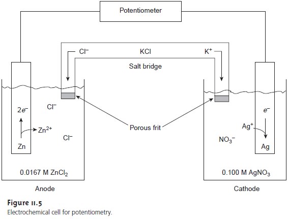
By convention, the electrode on the left is considered to be the anode, where
oxidation occurs
Zn(s) < = = = = > Zn2+(aq)+ 2e–
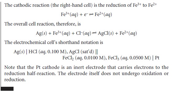
and the electrode on the right is the cathode, where reduction occurs
Ag+(aq)+ e– < = = = = > Ag(s)
The electrochemical cell’s potential, therefore, is for the
reaction
Zn(s) + 2Ag+(aq) < = = = = > 2Ag(s)+ Zn2+(aq)
Also, by convention, potentiometric electrochemical cells
are defined such that the indicator electrode is the cathode (right
half-cell) and the reference electrode is the anode (left half-cell).
Shorthand Notation for Electrochemical Cells
Although Figure 11.5 provides a useful
picture of an electrochemical cell,
it does not provide a convenient repre-
sentation. A more
useful representation is a shorthand, or schematic, notation that uses symbols to indicate the
different phases present
in the electrochemical cell, as well as the composition of each phase. A vertical
slash (|) indicates a phase
boundary where a potential develops, and a comma
(,) separates species
in the same phase,
or two phases
where no potential develops. Shorthand cell
nota- tions begin with the anode
and continue to the cathode.
The electrochemical cell in
Figure 11.5, for example, is described in shorthand notation
as
Zn(s) | ZnCl2 (aq, 0.0167 M) || AgNO3 (aq, 0.100 M) | Ag(s)
The
double vertical slash
(||) indicates the salt bridge,
the contents of which are nor-
mally not indicated. Note that the double
vertical slash implies
that there is a poten- tial difference between the salt bridge
and each half-cell.
Potential and Concentration—The Nernst Equation
The potential of a potentio- metric electrochemical cell is given as
Ecell = Ec – Ea ……………………….11.1
where
Ec
and
Ea
are
reduction
potentials for
the
reactions
occurring
at
the cathode and anode. These
reduction potentials are a function
of the concentrations of those species
responsible for the electrode potentials, as given by the Nernst equation
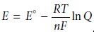
where E° is the standard-state reduction potential, R is the gas constant, T is the temperature in Kelvins, n is
the number of electrons involved
in the reduction reaction, F is Faraday’s constant, and Q is
the reaction quotient.* Under typical laboratory
conditions (temperature of 25 °C or 298 K) the Nernst equation
becomes
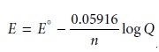 11.2
11.2
where E is given
in volts.
Using equation 11.2 the potential of the anode and cathode in
Figure 11.5 are
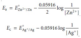
Note, again, that the Nernst
equations for both Ec and Ea are written for reduction
reactions. The cell
potential, therefore, is
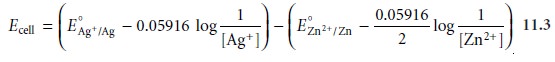
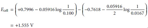
Substituting known values
for the standard-state reduction potentials (see Appen-
dix 3D) and the concentrations of Ag+ and Zn2+, gives a potential for the electro- chemical cell in Figure 11.5 of
In potentiometry, the concentration of analyte in the cathodic
half-cell is gen- erally unknown, and the measured cell potential is used to determine its concentra-
tion. Thus, if the potential for the cell
in Figure 11.5
is measured at +1.50 V, and the concentration of Zn2+ remains at 0.0167 M, then the concentration of Ag+ is
deter- mined by making
appropriate substitutions to equation 11.3
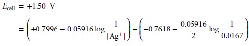
Solving for [Ag+] gives its concentration as 0.0118 M.
Despite the apparent
ease of determining an analyte’s concentration using the Nernst equation, several problems make this approach
impractical. One problem
is that standard-state potentials are temperature-dependent, and
most values listed
in reference tables are for a temperature of 25 °C. This difficulty can be overcome
by maintaining the electrochemical cell at a temperature of 25 °C or by measuring the standard-state potential at the desired temperature.
Another problem is that the Nernst equation
is a function of activities, not con- centrations.* As a result,
cell potentials may show significant matrix effects. This problem is compounded when the analyte
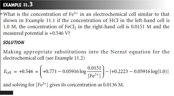
participates in additional equilibria. For
example, the standard-state potential for the Fe3+/Fe2+ redox couple
is +0.767 V in
1 M
HClO4, +0.70 V in 1 M HCl, and +0.53
in 10 M HCl. The shift toward
more negative potentials with an increasing concentration of HCl is due to chloride’s ability to form stronger complexes with Fe3+ than with
Fe2+. This
problem can be minimized by replacing the
standard-state potential with a matrix-dependent for- mal potential. Most tables of standard-state potentials also include a list of selected
formal potentials (see Appendix 3D).
A more serious
problem is the presence of additional potentials in the electro- chemical cell, not accounted for by equation 11.1. In writing
the shorthand nota- tion for the electrochemical cell in Figure
11.5, for example, we use a double slash (||) for the salt bridge, indicating that a potential difference exists at the interface between each end of the salt bridge and the solution
in which it is immersed. The origin of this potential, which
is called a liquid junction
potential, and its signifi-
cance are discussed in the following section.
Liquid Junction Potentials
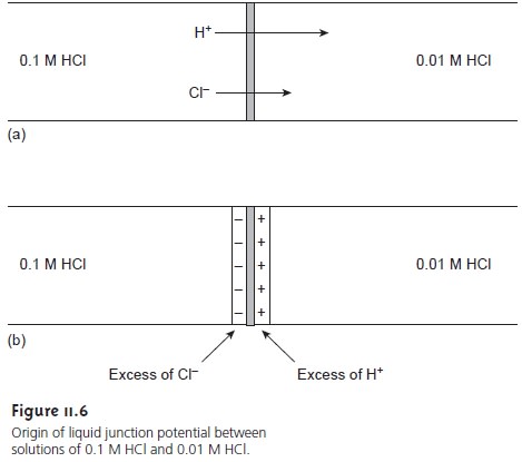
A liquid junction potential develops at
the interface between any two ionic solutions that differ in composition and for which
the mo- bility of the ions differs. Consider, for example, solutions of 0.1 M HCl and 0.01 M HCl
separated by a porous membrane (Figure 11.6a). Since
the concentration of HCl
on the left side of the membrane
is greater than that on the right
side of the membrane, there is a net diffusion of H+ and Cl– in the direction of the arrows.
The mobility of H+, however,
is greater than that for Cl–, as shown by the difference in the lengths of their respective arrows. As a result, the
solution on the
right side of the
membrane develops an excess of H+ and has a positive
charge (Figure 11.6b).
Simul- taneously, the solution on the left side of the membrane
develops a negative
charge due to the greater
concentration of Cl–. The difference in potential across
the mem- brane is called a liquid junction
potential, Elj.
The magnitude of the liquid
junction potential is determined by the ionic
com- position of the solutions on the two sides of the interface and may be as large
as 30–40 mV. For
example, a liquid
junction potential of 33.09 mV has been
measured at the interface between solutions of 0.1 M HCl and
0.1 M NaCl.2 The magnitude of a salt bridge’s
liquid junction potential is minimized by using a salt, such as KCl, for
which the mobilities of the
cation and anion
are approximately equal.
The magni- tude of the liquid junction potential
also is minimized by incorporating a high con- centration of the salt in the salt bridge.
For this reason
salt bridges are frequently
constructed using solutions that are saturated with KCl. Nevertheless, a small liquid junction potential, generally of unknown magnitude, is always present.
When the potential
of an electrochemical cell is measured, the contribution of the
liquid junction potential must be included. Thus, equation 11.1
is rewritten as
Ecell = Ec
– Ea + Elj
Since the junction
potential is usually
of unknown value,
it is normally impossible
to directly calculate the analyte’s concentration using the Nernst equation. Quanti- tative analytical work is possible.
Related Topics