Bipolar Junction Transistor [BJT] - Transistor as an oscillator | 12th Physics : UNIT 10a : Semiconductor Electronics
Chapter: 12th Physics : UNIT 10a : Semiconductor Electronics
Transistor as an oscillator
Transistor as an oscillator
An electronic oscillator basically converts dc energy into ac
energy of high frequency ranging from a few Hz to several MHz. Hence, it is a source of alternating
current or voltage. Unlike an amplifier, oscillator does not require any external
signal source.
Basically, there are two types of
oscillators: Sinusoidal and
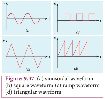
non-sinusoidal. Sinusoidal oscillators generate oscillations in the form of
sine waves at constant amplitude and frequency as shown in Figure 9.37(a).
Whereas non-sinusoidal oscillators generate complex non-sinusoidal waveforms
like Square-wave, Triangular-wave or
Sawtooth- wave as shown in Figure 9.36(b).

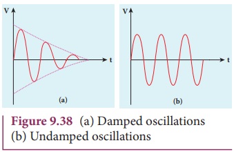
Sinusoidal oscillations can be of
two types: Damped and undamped. If
the amplitude of the electrical oscillations decreases with time due to energy
loss, it is called damped oscillations as shown in Figure 9.38(a). On the other
hand, the amplitude of the electrical oscillations remains constant with time
in undamped oscillations as shown in Figure 9.38(b).
Transistor Oscillator
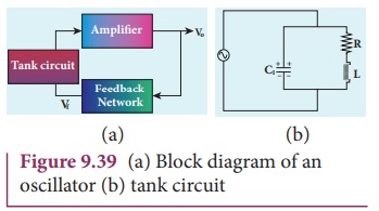
An oscillator circuit consists of a
tank circuit, an amplifier and a feedback circuit as shown in Figure 9.39. The
tank circuit generates electrical oscillations and acts as the ac input source
to the transistor amplifier. Amplifier amplifies the input ac signal. The feedback
circuit provides a portion of the output to the tank circuit to sustain the
oscillations without energy loss. Hence, an oscillator does not require an
external input signal. The output is said to be self-sustained.
Amplifier
The transistor amplifier circuit is
already explained in section {9.4.5}.
Feedback network
The circuit used to feedback a
portion of the output to the input is called the feedback network. If the
portion of the output fed to the input is in phase with the input, then the
magnitude of the input signal increases. It is necessary for sustained
oscillations.
Tank circuit
The LC tank circuit consists of an
inductance and a capacitor connected in parallel as shown in Figure 9.39.
Whenever energy is supplied to the tank circuit from a DC source, the energy is
stored in inductor and capacitor alternatively. This produces electrical
oscillations of definite frequency. (Refer section 4.9.1, Volume 1 of XII std.
Physics text book)
But in practical oscillator circuits
there will be loss of energy across resistors, inductor coils and capacitors. A
small amount of energy is used up in overcoming these losses during every cycle
of charging and discharging of the capacitor. Due to this, the amplitude of the
oscillations decreases gradually. Hence, the tank circuit produces damped
electrical oscillations. Therefore, in order to produce undamped oscillations,
a positive feedback is provided from the output circuit to the input circuit.
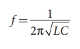
The frequency of oscillations is
determined by the values of L and C using the equation.
Barkhausen conditions for sustained oscillations
The following condition called
Barkhausen conditions should be satisfied for sustained oscillations in the
oscillator.
• The loop phase
shift must be 00 or integral multiples of 2Ď€.
• The loop gain must be unity. |Aβ| =1
Here, A→Voltage gain of the
amplifier,
β →feedback ratio; (fraction of the output
that is fed back to the input)
There are different types of
oscillator circuits based on the different types of tank circuits. Examples:
Hartley oscillator, Colpitt’s oscillator, Phase shift oscillator, and Crystal
oscillator.
Applications of oscillators
• to generate a
periodic sinusoidal or non sinusoidal wave forms
• to generate RF
carriers
• to generate audio
tones
• to generate clock signal in
digital circuits
• as sweep circuits in TV sets and
CRO
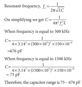
EXAMPLE 9. 9
Calculate the range of the variable capacitor that is to be used in a tuned-collector oscillator which has a fixed inductance of 150 ÎĽH. The frequency band is from 500 kHz to 1500 kHz.
Related Topics