Circuit symbol, Truth Table, Boolean equation, Logic operation | Digital Electronics - Logic gates | 12th Physics : UNIT 10a : Semiconductor Electronics
Chapter: 12th Physics : UNIT 10a : Semiconductor Electronics
Logic gates
DIGITAL ELECTRONICS
Logic gates
A logic gate is an electronic
circuit which functions based on digital signals. The logic gates are
considered as the basic building blocks of most of the digital systems. It has
one output with one or more inputs. There are three types of basic logic gates:
AND, OR, and NOT. The other logic gates are Ex-OR, NAND, and NOR. They can be
constructed from the basic logic gates.
Digital electronics deals with
logical operations. The variables are called logical variables. The operators
like logical addition (+) and logical multiplication (.) are called logical
operators. When the logical operators (+, .) operate on logical variables (A,
B), it gives logical constant (Y). The equation that represents this operation
is called logical statement.
For example,
Logical operator: +
Logical variable: A, B
Logical constant: Y
Logical Statement: Y = A + B
The possible combinations of inputs
and the corresponding output is given in table called truth table. The circuits
which perform the basic logical operations such as logical addition,
multiplication and inversion are discussed below.
AND gate
Circuit symbol
The circuit symbol of a two input
AND gate is shown in Figure 9.41(a). A and B are inputs and Y is the output. It
is a logic gate and hence A, B, and Y can have the value of either 1 or 0.
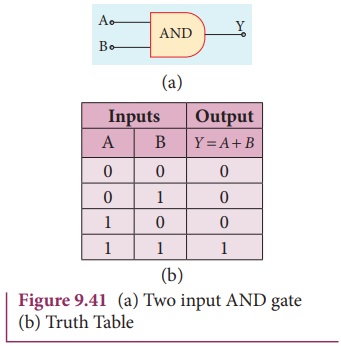
Boolean equation:
Y = A. B
It performs logical multiplication
and is different from arithmetic multiplication.
Logic operation
The output of AND gate is high (1)
only when all the inputs are high (1). The rest of the cases the output is low.
Hence the output of AND gate is high (1) only when all the inputs are high. It
is represented in the truth table (Figure 9.41(b)).
OR gate
Circuit Symbol
The circuit symbol of a two input OR
gate is shown in Figure 9.42(a). A and B are inputs and Y is the output.
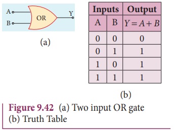
Boolean equation:
Y = A + B
It performs logical addition and is
different from arithmetic addition.
Logic operation
The output of OR gate is high (logic
1 state) when either of the inputs or both are high. The truth table of OR gate
is shown in Figure 9.42(b).
NOT gate
Circuit symbol
The circuit symbol of NOT gate is shown
in Figure 9.43(a). A is the input and Y is the output.
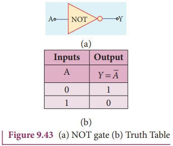
Boolean equation
Y = ![]()
Logic operation
The output is the complement of the
input. It is represented with an overbar. It is also called as inverter. The
truth table infers that the output Y is 1 when input A is 0 and vice versa. The
truth table of NOT is shown in Figure 9.43(b).
NAND gate
The circuit symbol of NAND gate is
shown in Figure 9.44(a). A and B are inputs and Y is the output.
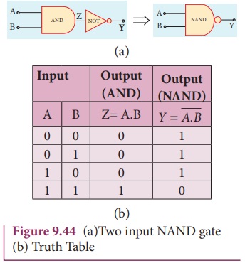
Boolean equation

Logic operation
The output Y equals the complement
of AND operation. The circuit is an AND gate followed by a NOT gate. Therefore,
it is summarized as NAND. The output is at logic zero only when all the inputs
are high. The rest of the cases, the output is high (Logic 1 state). The truth
table of NAND gate is shown in Figure 9.44(b).
NOR gate
Circuit symbol
The circuit symbol of NOR gate is
shown in Figure 9.45(a). A and B are inputs and Y is the output.
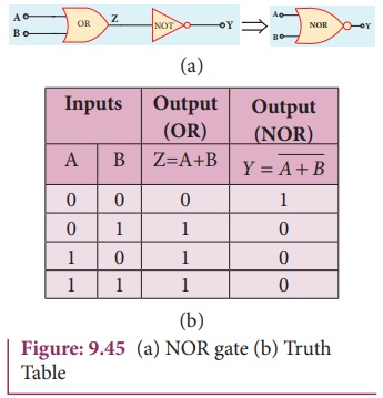
Boolean equation

Logic operation
Y equals the complement of OR
operation (A OR B). The circuit is an OR gate followed by a NOT gate and is
summarized as NOR.
The output is high when all the inputs
are low. The output is low for all other combinations of inputs. The truth
table of NOR gate is shown in Figure 9.45(b).
Ex-OR gate
Circuit symbol
The circuit symbol of Ex-OR gate is
shown in Figure 9.46(a). A and B are inputs and Y is the output. The Ex-OR
operation is denoted as ![]() .
.
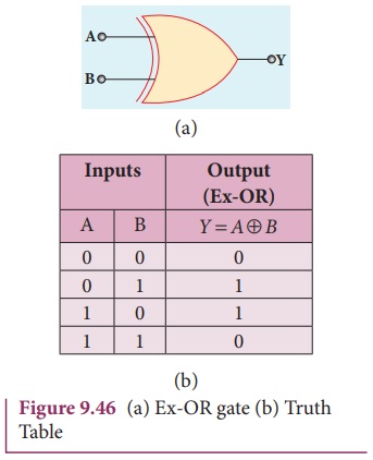
Boolean equation
Logic operation
The output is high only when either of the two inputs is high. In the case of an Ex-OR gate with more than two inputs, the output will be high when odd number of inputs are high. The truth table of Ex-OR gate is shown in Figure 9.46(b).
EXAMPLE 9. 11
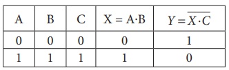
What is the output Y in the following circuit, when all the three inputs A, B, and C are first 0 and then 1?
Solution
EXAMPLE 9. 11
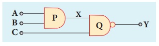
In the combination of the following
gates, write the Boolean equation for output Y in terms of inputs A and B.
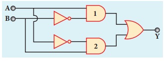
Solution
The output at the 1st AND gate: A![]()
The output at the 2nd AND gate: ![]() B
B
The output at the OR gate: Y = A. ![]() +
+ ![]() . B
. B
Related Topics