Chapter: 12th Physics : UNIT 10a : Semiconductor Electronics
Diode: Rectification
Rectification
The process of converting alternating current into direct
current is called rectification. In this section, we
will discuss two types of rectifiers namely, half wave rectifier and full wave
rectifier.
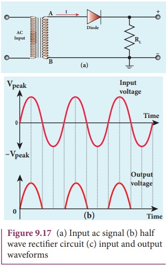
1. Half wave rectifier circuit
The half wave rectifier circuit is
shown in Figure 9.17(a). The circuit consists of a transformer, a p-n junction
diode and a resistor. In a half wave rectifier circuit, either a positive half
or the negative half of the AC input is passed through while the other half is
blocked. Only one half of the input wave reaches the output. Therefore, it is
called half wave rectifier. Here, a p-n junction diode acts as a rectifier
diode.
During the positive half cycle
When the positive half cycle of the
ac input signal passes through the circuit, terminal A becomes positive with
respect to terminal B. The diode is forward biased and hence it conducts. The current
flows ![]() through the load
resistor RL and the AC voltage developed across RL constitutes
the output voltage V0 and the waveform of the diode current is shown
in Figure 9.17(b).
through the load
resistor RL and the AC voltage developed across RL constitutes
the output voltage V0 and the waveform of the diode current is shown
in Figure 9.17(b).
During the negative half cycle
When the negative half cycle of the
ac input signal passes through the circuit, terminal A is negative with respect
to terminal B. Now the diode is reverse biased and does not conduct and hence
no current passes through RL. The reverse saturation current in a
diode is negligible. Since there is no voltage drop across RL, the
negative half cycle of ac supply is suppressed at the output. The output
waveform is shown in Figure 9.17b.
The output of the half wave rectifier
is not a steady dc voltage but a pulsating wave. This pulsating voltage can not
be used for electronic equipments. A constant or a steady voltage is required
which can be obtained with the help of filter circuits and voltage regulator
circuits.
Efficiency (η) is the ratio of the
output dc
power to the ac input power supplied to the circuit. Its value for half wave rectifier is 40.6 %
If the direction of the diode is
reversed, the negative half of the ac signal is passed through and the positive
half is blocked.
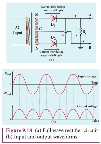
2. Full wave rectifier
The positive and negative half
cycles of the AC input signal pass through the full wave rectifier circuit and
hence it is called the full wave rectifier. The circuit is shown in Figure
9.18(a). It consists of two p-n junction diodes, a center tapped transformer,
and a load resistor (RL ) .
The centre is usually taken as the
ground or zero voltage reference point. Due to the centre tap transformer, the
output voltage rectified by each diode is only one half of the total secondary
voltage.
During positive half cycle
When the positive half cycle of the
ac input signal passes through the circuit, terminal M is positive, G is at
zero potential and N is at negative potential. This forward biases diode D1
and reverse biases diode D2. Hence, being forward biased, diode D1 conducts and current flows
along the path MD1AGC. As a result, positive half cycle of
the voltage appears across RL in
the direction G to C
During negative half cycle
When the negative half cycle of the
ac input signal passes through the circuit, terminal N is positive, G is at
zero potential and M is at negative potential. This forward biases diode D2
and reverse biases diode D1. Hence, being forward biased, diode D2
conducts and current flows along the path ND2
BGC. As a result, negative half cycle
of the voltage appears across RL
in the same direction from G to C.
Hence in a full wave rectifier both
postive and negative half cycles of the input signal pass through the load in
the same direction as shown in Figure 9.18(b). Though both positive and
negative half cycles of ac input are rectified, the output is still pulsating
in nature.
The efficiency (η) of full wave
rectifier is twice that of a half wave rectifier and is found to be 81.2 %. It
is because both the positive and negative half cycles of the ac input source
are rectified.
Centre tap transformer: There is a
facility to tap at halfway point in the secondary windings. This helps to
measure the induced voltage from one end of the secondary to the centre point.
If the centre tap point is grounded then the voltage applied across the
secondary will be divided by half. For example, if the voltage applied across
the secondary is 240 V, then the voltage across one end and the centre tap
point is +120 V and at the other end it is –120 V.
Related Topics