with Answers, Solution | Semiconductor Electronics | Physics - Example Solved Numerical Problems | 12th Physics : UNIT 10a : Semiconductor Electronics
Chapter: 12th Physics : UNIT 10a : Semiconductor Electronics
Example Solved Numerical Problems
Junction diode - Numerical Problems Questions with Answers, Solution
EXAMPLE 9. 1
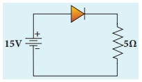
An ideal diode and a 5 ╬® resistor are connected in series with a 15 V power supply as shown in figure below. Calculate the current that flows through the diode.
Solution
The diode is forward biased and it is an ideal one. Hence, it acts like a closed switch with no barrier voltage. Therefore, current that flows through the diode can be calculated using OhmŌĆÖs law.
V = IR
I =V/R = 15/5 = 3 A
EXAMPLE 9. 2
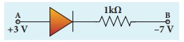
Consider an ideal junction diode. Find the value of current flowing through AB is
Solution
The barrier potential of the diode is neglected as it is an ideal diode.
The value of current flowing through AB can be obtained by using OhmŌĆÖs law
I = V/R = 3 - (-7) / 1├Ś 103 /103 = 10 =10-2 A = 10mA
Zener diode - Numerical Problems Questions with Answers, Solution
EXAMPLE: 9.3
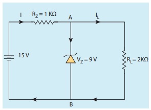
Find the current through the Zener diode when the load resistance is 1 K╬®. Use diode approximation.
Solution
Voltage across AB is VZ = 9V
Voltage drop across R = 15 - 9 = 6V
Therefore current through the resistor R,
I = 6 / 1├Ś103 =6 mA
Voltage across the load resistor = VAB = 9V
Current through load resistor
IL = VAB/RL = 9 / 2├Ś103 = 4.5 mA
The current through the Zener diode,
IZ = I ŌłÆIL =6 mAŌłÆ 4.5mA =1.5 mA
Optoelectronic devices using Diodes - Numerical Problems Questions with Answers, Solution
EXAMPLE 9.4
Determine the wavelength of light emitted from LED which is made up of GaAsP semiconductor whose forbidden energy gap is 1.875 eV. Mention the colour of the light emitted (Take h = 6.6 ├Ś 10-34 Js).
Solution
Eg = hc / ╬╗
Therefore
╬╗= hc / Eg = 6.6├Ś10ŌłÆ34 ├Ś3├Ś108 / 1.875├Ś1.6├Ś10ŌłÆ19
= 660 nm
The wavelength 660 nm corresponds to red colour light.
Transistor action in the common base mode - Numerical Problems Questions with Answers, Solution
EXAMPLE 9. 5
In a transistor connected in the common base configuration, ╬▒=0.95 , IE =1 mA . Calculate the values of IC and IB .
Solution
╬▒= IC/IE
IC =╬▒ IE =0.95├Ś1=0.95 mA
IE = IB + IC
Ōł┤ IB = IC ŌłÆIE =1ŌłÆ0.95=0.05 mA
Transistor in Common Emitter Mode - Numerical Problems Questions with Answers, Solution
EXAMPLE 9. 6
The output characteristics of a transistor connected in common emitter mode is shown in the figure. Determine the value of IC when VCE = 15 V. Also determine the value of IC when VCE is changed to 10 V.
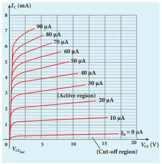
When VCE = 15 V, IC = 1.5 ╬╝A
When VCE is changed to 10 V, IC = 1.4 ╬╝A
The collector current is independent of the collector- emitter voltage in the active region.
EXAMPLE 9.7
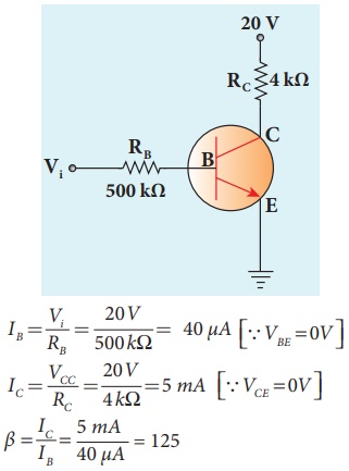
In the circuit shown in the figure, the input voltage Vi is 20 V, VBE = 0 V and VCE = 0 V. What are the values of IB , IC , ╬▓?
Bipolar Junction Transistor [BJT] - Numerical Problems Questions with Answers, Solution
EXAMPLE: 9.8
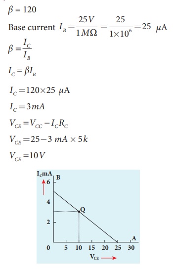
The current gain of a common emitter transistor circuit shown in figure is 120. Draw the dc load line and mark the Q point on it. (VBE to be ignored).
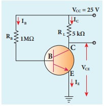
Solution
╬▓ = 120
Transistor as an oscillator - Numerical Problems Questions with Answers, Solution
EXAMPLE 9. 9
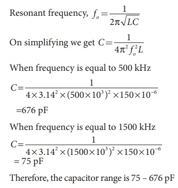
Calculate the range of the variable capacitor that is to be used in a tuned-collector oscillator which has a fixed inductance of 150 ╬╝H. The frequency band is from 500 kHz to 1500 kHz.
Logic gates - Numerical Problems Questions with Answers, Solution
EXAMPLE 9. 10
What is the output Y in the following circuit, when all the three inputs A, B, and C are first 0 and then 1?
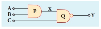
Solution
EXAMPLE 9. 11
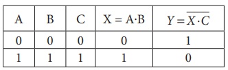
In the combination of the following gates, write the Boolean equation for output Y in terms of inputs A and B.
Solution
The output at the 1st AND gate: A![]()
The output at the 2nd AND gate: ![]() B
B
The output at the OR gate: Y = A. ![]() +
+ ![]() . B
. B
De MorganŌĆÖs Theorem - Numerical Problems Questions
with Answers, Solution
EXAMPLE: 9 . 12
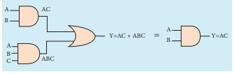
Simplify the Boolean identity
AC + ABC = AC
Solution
Step 1: AC (1 + B) = AC.1 [OR law-2]
Step 2: AC . 1 = AC [AND law ŌĆō 2]
Therefore, AC + ABC = AC
Circuit Description
Thus the given statement is proved.
Space Wave Propagation - Numerical Problems Questions with Answers, Solution
EXAMPLE 10.1
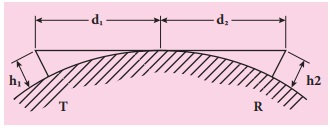
A transmitting antenna has a height of 40 m and the height of the receiving antenna is 30 m. What is the maximum distance between them for line-of-sight communication? The radius of the earth is 6.4├Ś106 m.
Solution:
The total distance d between the transmitting and receiving antennas will be the sum of the individual distances of coverage.
d = d1 +d2
= ŌłÜ(2Rh┬Ł) + ŌłÜ(2Rh2)
= ŌłÜ2ŌłÜR (ŌłÜh1 + ŌłÜh2)
= ŌłÜ[2 ├Ś 6.4 ├Ś106] ├Ś ( ŌłÜ40 + ŌłÜ30 )
=16 ├Ś102 ŌłÜ5 ├Ś(6.32 + 5.48)
=42217m= 42.217 km
Numerical Problems
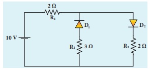
1. The given circuit has two ideal diodes connected as shown in figure below. Calculate the current flowing through the resistance R1 [Ans: 2.5 A]
Solution:
Barrier potential for ideal diode is zero. The diode D1 is reverse biased, so it will block the current and diode D2 is forward biased, so it will pass the current.
The given circuit becomes
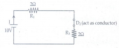
Effective resistance Reff = R1 + R3 = 4╬®
Current through R1 = V/Reff = 10/4 = 2.5A
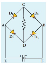
2. Four silicon diodes and a 10 ╬® resistor are connected as shown in figure below. Each diode has a resistance of 1╬®. Find the current flows through the 18╬® resistor. [Ans: 0.13 A]
Solution:
In the given circuit D2 & D3 are in forward bias so they conduct current while D1 &D4 are in reverse bias so they do not conduct current. So the equivalents circuit will be
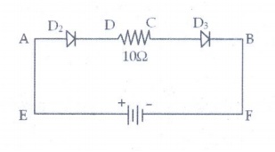
the effective resistance is Reff
= 1╬® + 10╬® + 1╬® = 12╬®
Here silicon diodes are used
Ōł┤ Barrier potential for Si is 0.7 V
Net potential (Vnet) = 3 ŌĆō 0.7 - 0.7
Vnet = 1.6 V
Current (I) = Vnet / R eff = 1.6 / 12 = 0.133A
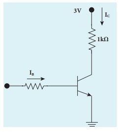
3. Assuming VCEsat = 0.2 V and ╬▓ = 50, find the minimum base current (IB) required to drive the transistor given in the figure to saturation. [Ans: 56 ┬ĄA]
Solution;
VCE = 0.2V
Rc = 1k╬®
╬▓ =50
Vcc = 3V
I B = ?
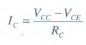
Ic = [ VCC ŌĆō VCE ] / RC
= (3-0.2) / 103
= 2.8 ├Ś 10-3 A
= 2.8 mA
╬▓= IC/IB
Ōł┤ IB = IC / ╬▓ = 2.8 ├Ś 10-3 / 50 = 0.056├Ś 10-3
= 56 ├Ś 10-6 A
IB=56╬╝A
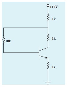
4. A transistor having ╬▒ =0.99 and VBE = 0.7V, is given in the circuit. Find the value of the collector current.
[Ans: 5.33 mA]
Given data:
╬▒ =0.99
VBE = 0.7V
IC=?
Solution:
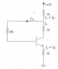
Tranistor is in saturation region.
Ōł┤ Ic = Ic(sat)
IC and IB are independent
VCE(sat) = 0.2 V, VBE(sat) = 0.8 V for silicon transistor (ie, standard value)
Apply KVR across B-E loop:
V1k + V10k + VBE sat + V1k = VCC
Ōł┤ 1(IC + IB) + 10 IB + 0.8 + 1 (IC + IB) = 12
2 IC + 12 IB = 11.2 ŌĆ”ŌĆ”ŌĆ”ŌĆ”ŌĆ”(1)
Apply KVR across C-E loop:
V1k + V1k + VCE sat + V1k = VCC
l(IC + IB) + 1 IC + 0.2 + I(IC + IB) = 12
3IC + 2IB = 11.8 ŌĆ”ŌĆ”ŌĆ”ŌĆ”ŌĆ”ŌĆ”.(2)
Solve the equation (1) and (2)
IB = 0.3125 mA
IC = 3.725 mA Ōēł 3.73 mA
5. In the circuit shown in the figure, the BJT has a current gain (╬▓) of 50. For an emitter ŌĆō base voltage VEB = 600 mV, calculate the emitter ŌĆō collector voltage VEC (in volts). [Ans: 2 V]
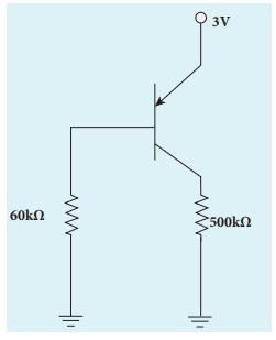
Given data:
╬▓ = 50
VE=3V
VEB=60 mV
RB=60K╬®
RE=500╬®
Solution:
VB=VEŌłÆVEB
VB = 3ŌłÆ0.6 = 2.4V
IB = VB/RB = 2.4 / 60├Ś103 = 40╬╝A
IC = ╬▓IB = 50├Ś40╬╝A = 2├Ś10-3 A = 2mA
VC = RCIC = 500├Ś2├Ś10-3 = 1V
VEC = VE-VC = 3-1 = 2V
VEC = 2V
6. Determine the current flowing through 3╬® and 4╬® resistors of the circuit given below. Assume that diodes D1 and D2 are ideal diodes.
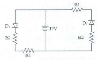
Solution:
The diode D2 is in reverse biased. So does not conduct current.
Ōł┤ current through 3╬® is = 0
The diode D1 is in forward biased, and it is an ideal diode. So the given circuit becomes as
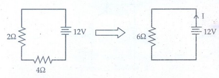
The current through 4╬® is
Ōł┤ I = V/R = 12/6 =2A
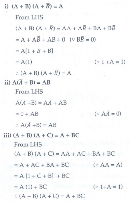
7. Prove the following Boolean expressions using the laws and theorems of Boolean algebra.
i) (A + B) (A + ![]() ) = A
) = A
ii) A (![]() +B) = AB
+B) = AB
iii) (A + B) (A + C) = A + BC
Solution:
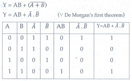
8. Verify the given Boolean equation A + ߊ╣B = A + B using truth table.
Solution:
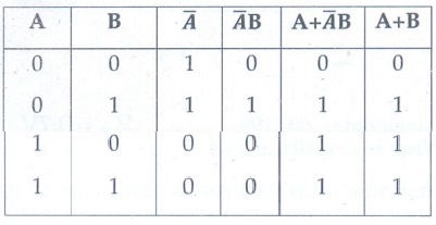
Hence, verified
9. In the given figure of a voltage regulator, a Zener diode of breakdown voltage 15V is employed. Determine the current through the load resistance, the total current and the current through the diode. Use diode approximation.
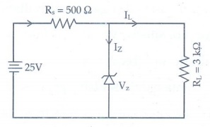
Solution:
Voltage across RL(VO) = Vz = 15V
Voltage across RS(VRS) = 25 -15 = 10V
current through RL is
IL = V0/RL = 15 / 3├Ś103 = 5├Ś10-3 A
IL = 5 mA
Current through RS is
I = VRS/RS = 10/500 = 20├Ś10-3A
I = 20mA
Current through Zener diode is
IZ=I-IL
= (20-5) ├Ś 10-3
Iz = 15mA
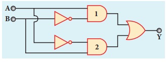
10. Write down Boolean equation for the output Y of the given circuit and give its truth table.
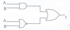
Solution:
Related Topics