Physics - Current Electricity: Exercises and Example Solved Numerical problems | 12th Physics : Current Electricity
Chapter: 12th Physics : Current Electricity
Current Electricity: Exercises and Example Solved Numerical problems
Numerical problems
1. The following graphs represent the current versus voltage and voltage versus current for the six conductors A,B,C,D,E and F. Which conductor has least resistance and which has maximum resistance?
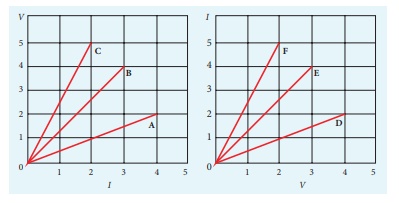
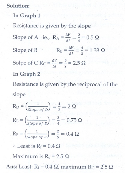
Ans: Least: RF = 0.4 Ōä”, maximum RC = 2.5 Ōä”
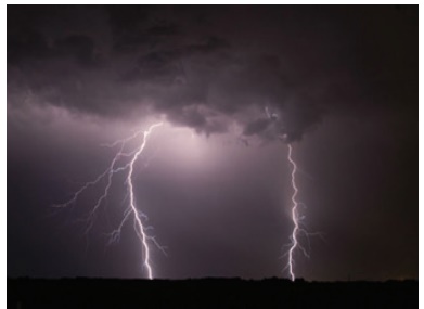
2. Lightning is very good example of natural current. In typical lightning, there is 109 J energy transfer across the potential difference of 5 ├Ś 107 V during a time interval of 0.2 s.
Using this information, estimate the following quantities (a) total amount of charge transferred between cloud and ground (b) the current in the lightning bolt (c) the power delivered in 0.2 s.
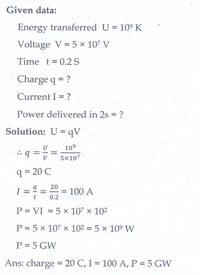
Ans: charge = 20 C, I = 100 A, P = 5 GW
3. A copper wire of 10-6 m2 area of cross section, carries a current of 2 A. If the number of electrons per cubic meter is 8 ├Ś 1028, calculate the current density and average drift velocity.
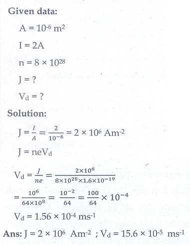
Ans: J = 2 ├Ś 106 AmŌłÆ2 ; vd= 15.6 ├Ś 10ŌłÆ5 msŌłÆ1
4. The resistance of a nichrome wire at 0┬║ C is 10 ╬®. If its temperature coefficient of resistance is 0.004/┬║C, find its resistance at boiling point of water. Comment on the result.
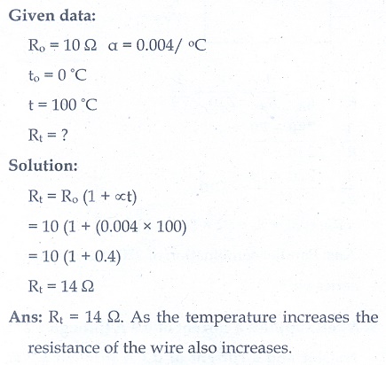
Ans: RT= 14 ╬®. As the temperature increases the resistance of the wire also increases.
5. The rod given in the figure is made up of two different materials.

Both have square cross sections of 3 mm side. The resistivity of the first material is 4 x 10⁻³ Ōä”.m and it is 25 cm long while second material has resistivity of 5 x 10⁻³ Ōä”.m and is of 70 cm long. What is the resistivity of rod between its ends?
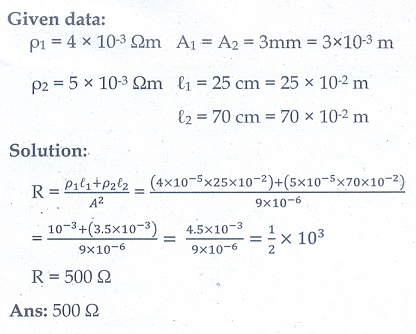
Ans: 500 Ōä”
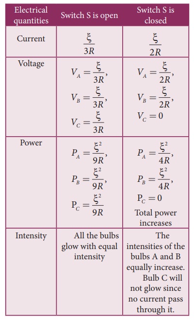
6. Three identical lamps each having a resistance R are connected to the battery of emf as shown in the figure.
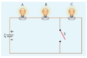
Suddenly the switch S is closed. (a) Calculate the current in the circuit when S is open and closed (b) What happens to the intensities of the bulbs A,B and C. (c) Calculate the voltage across the three bulbs when S is open and closed (d) Calculate the power delivered to the circuit when S is opened and closed (e) Does the power delivered to the circuit decreases, increases or remain same?
Ans:
7. The current through an element is shown in the figure. Determine the total charge that pass through the element at a) t = 0 s, b) t = 2 s, c) t = 5s
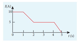
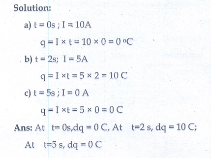
Ans: At t= 0s,dq = 0 C, At t=2 s, dq = 10 C; At t=5 s, dq = 0 C
8. An electronics hobbyist is building a radio which requires 150 ╬® in her circuit, but she has only 220 ╬®, 79 ╬® and 92 ╬® resistors available. How can she connect the available resistors to get desired value of resistance?
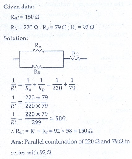
Ans: Parallel combination of 220 ╬® and 79 ╬® in series with 92 ╬®
9. A cell supplies a current of 0.9 A through a 2 ╬® resistor and a current of 0.3 A through a 7 ╬® resistor. Calculate the internal resistance of the cell.
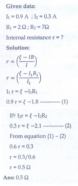
Ans: 0.5 ╬®
10. Calculate the currents in the following circuit.
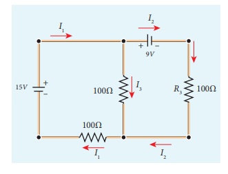
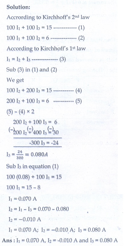
Ans : I1 = 0.070 A, I2 = -0.010 A and I3 = 0.080 A
11. A potentiometer wire has a length of 4 m and resistance of 20 ╬®. It is connected in series with resistance of 2980 ╬® and a cell of emf 4 V. Calculate the potential along the wire.
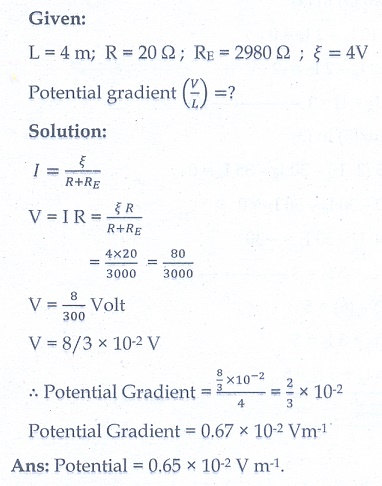
Ans: Potential = 0.65 ├Ś 10-2 V m-1.
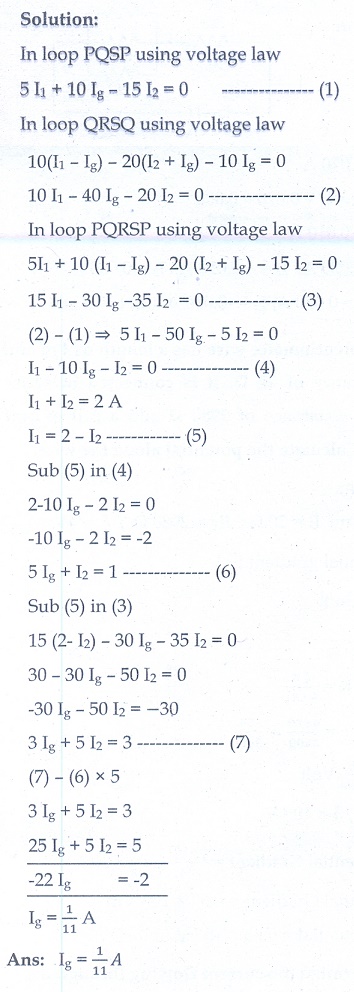
12. Determine the current flowing through the galvanometer (G) as shown in the figure.
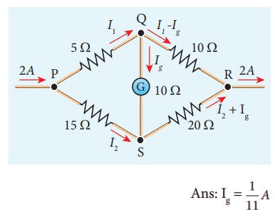
13. Two cells each of 5V are connected in series across a 8 ╬® resistor and three parallel resistors of 4 ╬®, 6 ╬® and 12 ╬®. Draw a circuit diagram for the above arrangement. Calculate i) the current each resistor
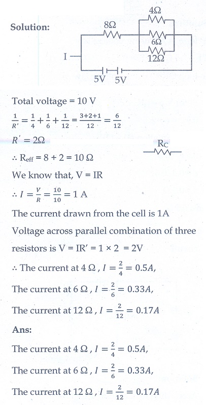
Ans: The current at 4 Ōä” ,I = 2/4 = 0 .5A, the current at 6 Ōä”, I = 2/6 = 0.33A , the current at 12 Ōä”, I = 2/12 = 0 . 17 A
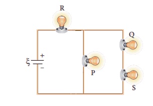
14. Four light bulbs P, Q, R, S are connected in a circuit of unknown arrangement. When each bulb is removed one at a time and replaced, the following behavior is observed.
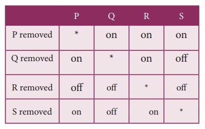
Draw the circuit diagram for these bulbs.
Ans
15. In a potentiometer arrangement, a cell of emf 1.25 V gives a balance point at 35 cm length of the wire. If the cell is replaced by another cell and the balance point shifts to 63 cm, what is the emf of the second cell?
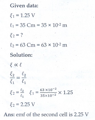
Ans: emf of the second cell is 2.25 V
Electric Current: Solved Example Problems
EXAMPLE 2.1
Compute the current in the wire if a charge of 120 C is flowing through a copper wire in 1 minute.
Solution
The current (rate of flow of charge) in the wire is
I = Q/t = 120/60 = 2A
EXAMPLE 2.2
If an electric field of magnitude 570 N C-1, is applied in the copper wire, find the acceleration experienced by the electron.
Solution:
E = 570 N C-1, e = 1.6 ├Ś 10-19 C, m = 9.11 ├Ś 10-31 kg and a = ?
F = ma = eE
a = eE/m = 570├Ś1 .6├Ś10ŌłÆ19/9 .11├Ś10-31
= 912 ├Ś10ŌłÆ19 ├Ś1031 / 9 .11
= 1.001 ├Ś 1014 m s-2
EXAMPLE 2.3
A copper wire of cross-sectional area 0.5 mm2 carries a current of 0.2 A. If the free electron density of copper is 8.4 ├Ś 1028 m-3 then compute the drift velocity of free electrons.
Solution
The relation between drift velocity of electrons and current in a wire of cross-sectional area A is
vd = I/ ne A

vd = 0.03 x 10⁻³ m s-1
EXAMPLE 2.4
Determine the number of electrons flowing per second through a conductor, when a current of 32 A flows through it.
Solution
I = 32 A , t = 1 s
Charge of an electron, e = 1.6 ├Ś 10-19 C
The number of electrons flowing per second, n =?
I = q/t = ne/t
n = It/e
n = 32├Ś1 / 1 .6├Ś10ŌłÆ19 C
n = 20 ├Ś 1019 = 2 ├Ś 1020 electrons
OHMŌĆÖS LAW: Solved Example Problems
EXAMPLE 2.5
A potential difference across 24 ╬® resistor is 12 V. What is the current through the resistor?
Solution
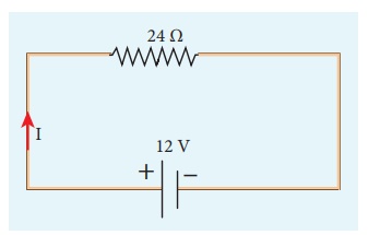
V = 12 V and R = 24 ╬®
Current, I = ?
From OhmŌĆÖs law, I = V/R = 12/24 = 0 .5 A
Resistivity: Solved Example Problems
EXAMPLE 2.6
The resistance of a wire is 20 ╬®. What will be new resistance, if it is stretched uniformly 8 times its original length?
Solution
R1 = 20 ╬®, R2= ?
Let the original length (l1) be l.
The new length, l2 = 8l1 (i.,e) l2 =8l
The original resistance, R = Žü [ l1 / A1]
The new resistance
R2 = 
Though the wire is stretched, its volume is unchanged.
Initial volume = Final volume
A1l1= A2l2 , A1l = A28l
A1 / A2 = 8l / l = 8
By dividing equation R2 by equation R1, we get
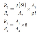
Substituting the value of A1/A2, we get
R2 / R1 = 8 ├Ś8 = 64 2
R2 = 64 ├Ś 20=1280 ╬®
Hence, stretching the length of the wire has increased its resistance.
EXAMPLE 2.7
Consider a rectangular block of metal of height A, width B and length C as shown in the figure.
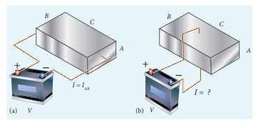
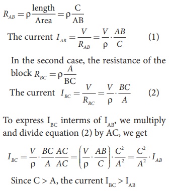
If a potential difference of V is applied between the two faces A and B of the block (figure (a)), the current IAB is observed. Find the current that flows if the same potential difference V is applied between the two faces B and C of the block (figure (b)). Give your answers in terms of IAB.
Solution
In the first case, the resistance of the block
Resistors in series and parallel:
EXAMPLE 2.8
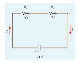
Calculate the equivalent resistance for the circuit which is connected to 24 V battery and also find the potential difference across 4 ╬® and 6 ╬® resistors in the circuit.
Solution
Since the resistors are connected in series, the effective resistance in the circuit
= 4 ╬® + 6 ╬® = 10 ╬®
The Current I in the circuit= V/ Req = 24/10 = 2 .4 A
Voltage across 4╬® resistor
V1 = IR1 = 2 . 4 A├Ś 4 ╬® = 9.6V
Voltage across 6 ╬® resistor
V2 = IR1 = 2 . 4 A├Ś 6 ╬® =14 .4V
EXAMPLE 2.9
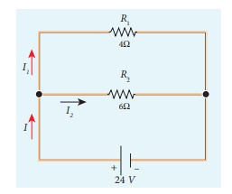
Calculate the equivalent resistance in the following circuit and also find the current I, I1 and I2 in the given circuit.
Solution
Since the resistances are connected in parallel, therefore, the equivalent resistance in the circuit is
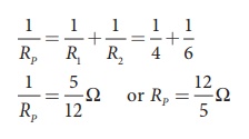
The resistors are connected in parallel, the potential (voltage) across each resistor is the same.
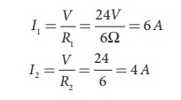
The current I is the total of the currents in the two branches. Then,
I = I1 + I2= 6 A + 4 A = 10 A
EXAMPLE 2.10
When two resistances connected in series and parallel their equivalent resistances are 15 ╬® and 56/15 ╬® respectively. Find the individual resistances.
Solution
Rs = R1 + R2 = 15 ╬® (1)
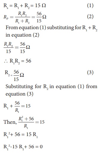
The above equation can be solved using factorisation.
R12-8 R1-7 R1+ 56 = 0
R1 (R1ŌĆō 8) ŌĆō 7 (R1ŌĆō 8) = 0
(R1ŌĆō 8) (R1ŌĆō 7) = 0
If (R1= 8 ╬®)
using in equation (1)
8 + R2 = 15
R2 = 15 ŌĆō 8 = 7 ╬® ,
R2 = 7 ╬® i.e , (when R1 = 8 ╬® ; R2 = 7 ╬®)
If (R1= 7 ╬®)
Substituting in equation (1)
7 + R2 = 15
R2 = 8 ╬® , i.e , (when R1 = 8 ╬® ; R2 = 7 ╬® )
EXAMPLE 2.11
Calculate the equivalent resistance between A and B in the given circuit.

Solution
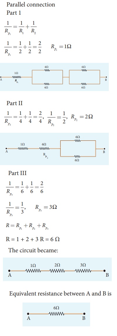
EXAMPLE 2.12
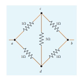
Five resistors are connected in the configuration as shown in the figure. Calculate the equivalent resistance between the points a and b.
Solution
Case (a)
To find the equivalent resistance between the points a and b, we assume that current is entering the junction a. Since all the resistances in the outside loop are the same (1╬®), the current in the branches ac and ad must be equal. So the electric potential at the point c and d is the same hence no current flows into 5 ╬® resistance. It implies that the 5 ╬® has no role in determining the equivalent resistance and it can be removed. So the circuit is simplified as shown in the figure.
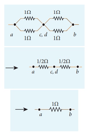
The equivalent resistance of the circuit between a and b is Req = 1╬®
Temperature dependence of resistivity: Solved Example Problems
EXAMPLE 2.13
If the resistance of coil is 3 ╬® at 20 0C and ╬▒ = 0.004/0C then determine its resistance at 100 0C.
Solution
R0= 3 ╬®,ŌĆā T = 100┬║C,ŌĆā T0 = 20┬║C
╬▒ = 0.004/┬║C,ŌĆā RT = ?
RT= R0(1 + ╬▒(T-T0))
R100 = 3(1 + 0.004 ├Ś 80)
R100 = 3(1 + 0.32)
R100 = 3(1.32)
R100 = 3.96 ╬®
EXAMPLE 2.14
Resistance of a material at 10┬║C and 40┬║C are 45 ╬® and 85 ╬® respectively. Find its temperature co-efficient of resistance.
Solution
T0 = 10┬║C, T = 40┬║C, R0= 45 ╬® , R = 85 ╬®
α = 1/R . ΔR /ΔT

╬▒ = 0.0296 per ┬║C
Energy and Power in Electrical Circuits: Solved Example Problems
EXAMPLE 2.15
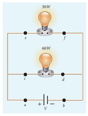
A battery of voltage V is connected to 30 W bulb and 60 W bulb as shown in the figure. (a) Identify brightest bulb (b) which bulb has greater resistance? (c) Suppose the two bulbs are connected in series, which bulb will glow brighter?
Solution
(a) The power delivered by the battery P = VI. Since the bulbs are connected in parallel, the voltage drop across each bulb is the same. If the voltage is kept fixed, then the power is directly proportional to current (P ŌłØ I). So 60 W bulb draws twice as much as current as 30 W and it will glow brighter then others.
(b) To calculate the resistance of the bulbs, we use the relation P = V2 / R . In both the bulbs, the voltage drop is the same, so the power is inversely proportional to the resistance or resistance is inversely proportional to the power (RŌłØ1/P) . It implies that, the 30W has twice as much as resistance as 60 W bulb.
(c) When these two bulbs are connected in series, the current passing through each bulb is the same. It is equivalent to two resistors connected in series. The bulb which has higher resistance has higher voltage drop. So 30W bulb will glow brighter than 60W bulb. So the higher power rating does not always imply more brightness and it depends whether bulbs are connected in series or parallel.
EXAMPLE 2.16
Two electric bulbs marked 20 W ŌĆō 220 V and 100 W ŌĆō 220 V are connected in series to 440 V supply. Which bulb will be fused?
Solution
To check which bulb will be fused, the voltage drop across each bulb has to be calculated.
The resistance of a bulb,
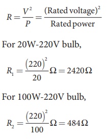
Both the bulbs are connected in series. So the current which passes through both the bulbs are same. The current that passes through the circuit, I = V /Rtot.
Rtot = ( R1 + R2 )
Rtot = ( 484 +2420) ╬® = 2904╬®
I = 440V/2904╬® Ōēł 0.151A
The voltage drop across the 20W bulb is
V1 = IR1 = 440/2904 ├Ś 2420 Ōēł 366.6 V
The voltage drop across the 100W bulb is
V2 = IR2 = 440/2904 ├Ś 484 Ōēł 73.3 V
The 20 W bulb will be fused because its voltage rating is only 220 V and 366.6 V is dropped across it.
EXAMPLE 2.17
A battery has an emf of 12 V and connected to a resistor of 3ŌĆå╬®. The current in the circuit is 3.93ŌĆåA. Calculate (a) terminal voltage and the internal resistance of the battery (b) power delivered by the battery and power delivered to the resistor
Solution
The given values I = 3.93 A, ╬Š = 12 V, R = 3 Ōä”
(a) The terminal voltage of the battery is equal to voltage drop across the resistor
V = IR = 3.93 ├Ś 3 = 11.79 V
The internal resistance of the battery,
r = |╬Š ŌĆōV / V| R = | 12 ŌłÆ11 .79 /11 .79 | ├Ś 3 = 0.05 ╬®
The power delivered by the battery P = I╬Š = 3.93 ├Ś 12 = 47.1 W
The power delivered to the resistor = I2 R = 46.3 W
The remaining power = (47.1ŌĆåŌĆōŌĆå46.3) P = 0.772 W is delivered to the internal resistance and cannot be used to do useful work. (it is equal to I2 r).
Cells in series: Solved Example Problems
EXAMPLE 2.18
From the given circuit,
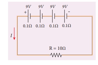
Find
i) Equivalent emf of the combination
ii) Equivalent internal resistance
iii) Total current
iv) Potential difference across external resistance
v) Potential difference across each cell
Solution
i) Equivalent emf of the combination ╬Šeq = n╬Š = 4 9 = 36 V
ii) Equivalent internal resistance req = nr = 4 ├Ś 0.1 = 0.4 ╬®
iii) Total current I = n╬Š / R +nr
= [4 ├Ś9] / 10 + ( 4 ├Ś0.1)
= [4 ├Ś9] / [10 +0 .4] = 36 /10.4
I = 3.46 A
iv) Potential difference across external resistance V = IR = 3.46 ├Ś 10 = 34.6 V. The remaining 1.4 V is dropped across the internal resistance of cells.
v) Potential difference across each cell V/n = 34.6/4 = 8 .65V
Cells in parallel: Solved Example Problems
EXAMPLE 2.19
From the given circuit
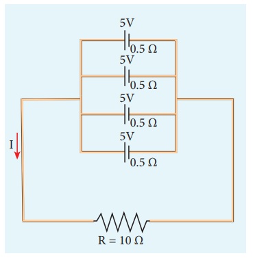
Find
i) Equivalent emf
ii) Equivalent internal resistance
iii) Total current (I)
iv) Potential difference across each cell
v) Current from each cell
Solution
i) Equivalent emf ╬Šeq = 5 V
ii) Equivalent internal resistance,
Req = r/n = 0 .5/4 = 0.125╬®
iii) total current,

I Ōēł 0.5 A
iv) Potential difference across each cell V = IR = 0.5 ├Ś 10 = 5 V
v) Current from each cell, I ŌĆ▓ = I/n
I ŌĆ▓ = 0.5/4 = 0.125 A
KirchhoffŌĆÖs first rule (Current rule or Junction rule): Solved Example Problems
EXAMPLE 2.20
From the given circuit find the value of I.
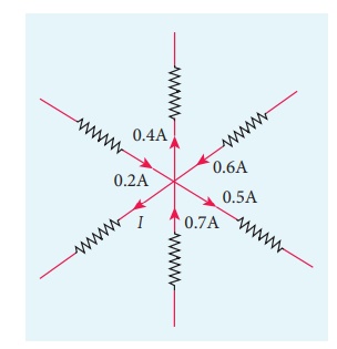
Solution
Applying KirchoffŌĆÖs rule to the point P in the circuit,
The arrows pointing towards P are positive and away from P are negative.
Therefore, 0.2A ŌĆō 0.4A + 0.6A ŌĆō 0.5A + 0.7A ŌĆō I = 0
1.5A ŌĆō 0.9A ŌĆō I = 0
0.6A ŌĆō I = 0
I = 0.6 A
KirchhoffŌĆÖs Second rule (Voltage rule or Loop rule) : Solved Example Problems
EXAMPLE 2.21
The following figure shows a complex network of conductors which can be divided into two closed loops like ACE and ABC. Apply KirchoffŌĆÖs voltage rule.
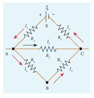
Solution
Thus applying KirchoffŌĆÖs second law to the closed loop EACE
I1R1 + I2R2 + I3R3 = ╬Š
and for the closed loop ABCA
I4R4 + I5R5-I2R2= 0
EXAMPLE 2.22
Calculate the current that flows in the 1ŌĆå╬® resistor in the following circuit.
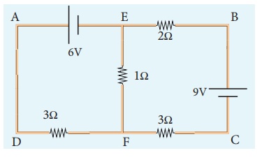
Solution
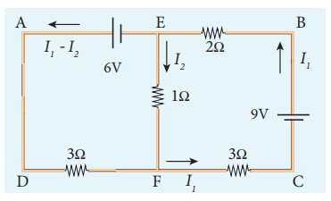
We can denote the current that flows from 9V battery as I1 and it splits into I2 and I1 ŌĆō I2 in the junction according KirchoffŌĆÖs current rule (KCR). It is shown below.
Now consider the loop EFCBE and apply KVR, we get
1I2 + 3I1 + 2I1 = 9
5I1 + I2 = 9 (1)
Applying KVR to the loop EADFE, we get
3 (I1 ŌĆō I2 ) ŌĆō 1I2 = 6
3I1 ŌĆō 4I2 = 6 (2)
Solving equation (1) and (2), we get
I1 = 1.83 A and I2 = -0.13 A
It implies that the current in the 1 ohm resistor flows from F to E.
WheatstoneŌĆÖs bridge : Solved Example Problems
EXAMPLE 2.23
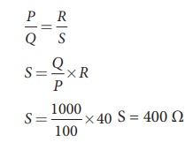
In a WheatstoneŌĆÖs bridge P = 100 ╬®, Q = 1000 ╬® and R = 40 ╬®. If the galvanometer shows zero deflection, determine the value of S.
Solution
EXAMPLE 2.24
What is the value of x when the WheatstoneŌĆÖs network is balanced?
P = 500 ╬®, Q = 800 ╬®, R = x + 400, S = 1000 ╬®
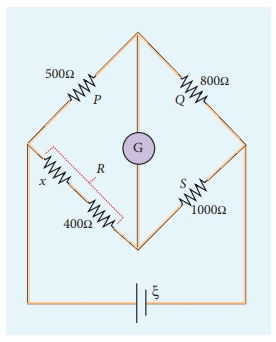
Solution
P/Q = R/S
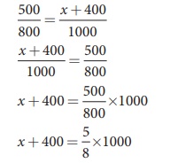
x + 400 = 0.625 ├Ś 1000
x + 400 = 625
x = 625 ŌĆō 400
x = 225 ╬®
Meter bridge : Solved Example Problems
EXAMPLE 2.25
In a meter bridge with a standard resistance of 15 ╬® in the right gap, the ratio of balancing length is 3:2. Find the value of the other resistance.
Solution
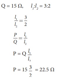
EXAMPLE 2.25
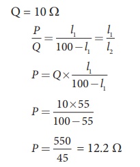
In a meter bridge, the value of resistance in the resistance box is 10 ╬®. The balancing length is l1 = 55 cm. Find the value of unknown resistance.
Solution
Q = 10 Ōä”
Heating Effect of Electric Current, JouleŌĆÖs law: Solved Example Problems
EXAMPLE 2.27
Find the heat energy produced in a resistance of 10 ╬® when 5 A current flows through it for 5 minutes.
Solution
R = 10 ╬®, I = 5 A, t = 5 minutes = 5 ├Ś 60 s
H = I2 R t
= 52 ├Ś 10 ├Ś 5 ├Ś 60
=25 ├Ś 10 ├Ś 300
=25 ├Ś 3000
=75000 J (or) 75 kJ
EXAMPLE 2.28
An electric heater of resistance 10 ╬® connected to 220 V power supply is immersed in the water of 1 kg. How long the electrical heater has to be switched on to increase its temperature from 30┬░C to 60┬░C. (The specific heat of water is s = 4200 J kg-1)
Solution
According to JouleŌĆÖs heating law H = I2 Rt
The current passed through the electrical heater = 220V/10╬® = 22 A
The heat produced in one second by the electrical heater H = I2 R
The heat produced in one second H = (22)2 x 10 = 4840 J = 4.84 k J. In fact the power rating of this electrical heater is 4.84 k W.
The amount of energy to increase the temperature of 1kg water from 30┬░C to 60┬░C is
Q = ms ŌłåT (Refer XI physics vol 2, unit 8)
Here m = 1 kg,
s = 4200 J kg-1,
ŌłåT = 30,
so Q = 1 ├Ś 4200 x 30 = 126 kJ
The time required to produce this heat energy t = Q/ I2R = 126 ├Ś103 / 4840 Ōēł 26 .03 s
Related Topics