Explanation, Formulas, Solved Example Problems - OhmŌĆÖs Law | 12th Physics : Current Electricity
Chapter: 12th Physics : Current Electricity
OhmŌĆÖs Law
OHMŌĆÖS LAW
The ohmŌĆÖs law can be
derived from the equation J = ŽāE. Consider a segment of wire of length l
and cross sectional area A as shown in Figure 2.7.
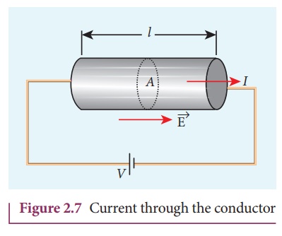
When a potential
difference V is applied across the wire, a net electric field is created in the
wire which constitutes the current. For simplicity, we assume that the electric
field is uniform in the entire length of the wire, the potential difference
(voltage V) can be written as
V = El
As we know, the
magnitude of current density
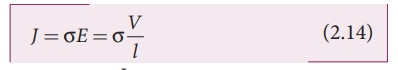
But J = I /A , so we write the
equation (2.14) as
I/A = Žā V/l .
By rearranging the above equation, we get
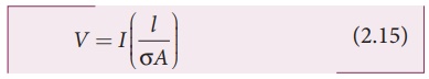
The quantity l/ŽāA is called resistance of
the conductor and it is denoted as R. Note that the resistance is directly
proportional to the length of the conductor and inversely proportional to area
of cross section.![]()
Therefore, the
macroscopic form of ohmŌĆÖs law can be stated as
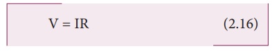
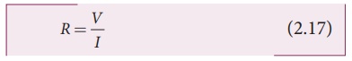
From the above equation,
the resistance is the ratio of potential difference across the given
conductor to the current passing through the conductor.
The SI unit of
resistance is ohm (╬®). From the equation (2.16), we infer that the graph
between current versus voltage is straight line with a slope equal to the
inverse of resistance R of the conductor. It is shown in the Figure 2.8 (a).
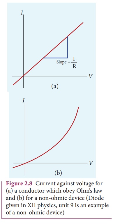
Materials for which the
current against voltage graph is a straight line through the origin, are said
to obey OhmŌĆÖs law and their behaviour is said to be ohmic as shown in Figure
2.8(a). Materials or devices that do not follow OhmŌĆÖs law are said to be
non-ohmic. These materials have more complex relationships between voltage and
current. A plot of I against V for a non-ohmic material is non-linear and they
do not have a constant resistance (Figure 2.8(b)).
EXAMPLE 2.5
A potential difference
across 24 ╬® resistor is 12 V. What is the current through the resistor?
Solution
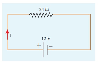
V = 12 V and R = 24 ╬®
Current, I = ?
From OhmŌĆÖs law, I = V/R
= 12/24 = 0 .5 A
1. Resistivity
In the previous section,
we have seen that the resistance R of any conductor is given by
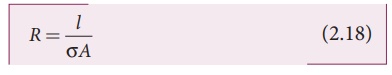
where Žā is called the
conductivity of the material and it depends only on the type of the material
used and not on its dimension.
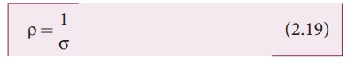
The resistivity of a
material is equal to the reciprocal of its conductivity.
Now we can rewrite
equation (2.18) using equation (2.19)
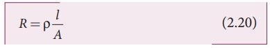
The resistance of a
material is directly proportional to the length of the conductor and inversely
proportional to the area of cross section of the conductor. The proportionality
constant Žü is called the resistivity of the material.![]()
![]()
If l = 1 m and A
= 1 m2, then the resistance R
= Žü. In other words, the electrical resistivity
of a material is defined as the resistance offered to current flow by a
conductor of unit length having unit area of cross section. The SI unit of
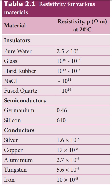
Žü is ohm-metre (╬® m). Based on the resistivity, materials are classified
as conductors, insulators and semi-conductors. The conductors have lowest
resistivity, insulators have highest resistivity and semiconductors have
resistivity greater than conductors but less than insulators. The typical
resistivity values of some conductors, insulators and semiconductors are given in
the Table 2.1
EXAMPLE 2.6
The resistance of a wire
is 20 ╬®. What will be new resistance, if it is stretched uniformly 8 times its
original length?
Solution
R1 = 20 ╬®, R2=
?
Let the original length
(l1) be l.
The new length, l2 = 8l1 (i.,e) l2 =8l
The original resistance,
R = Žü [ l1 / A1]
The new resistance
R2 = 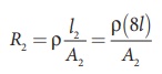
Though the wire is
stretched, its volume is unchanged.
Initial volume = Final
volume
A1l1= A2l2 , A1l = A28l
A1 / A2 =
8l / l = 8
By dividing equation R2 by equation R1, we get
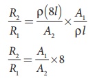
Substituting the value
of A1/A2, we get
R2 / R1 = 8 ├Ś8 = 64 2
R2 = 64 ├Ś
20=1280 ╬®
Hence, stretching the
length of the wire has increased its resistance.
EXAMPLE 2.7
Consider a rectangular
block of metal of height A, width B and length C as shown in the figure.
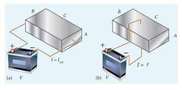
If a potential
difference of V is applied between the two faces A and B of the block (figure
(a)), the current IAB is observed. Find the current that flows if
the same potential difference V is applied between the two faces B and C of the
block (figure (b)). Give your answers in terms of IAB.
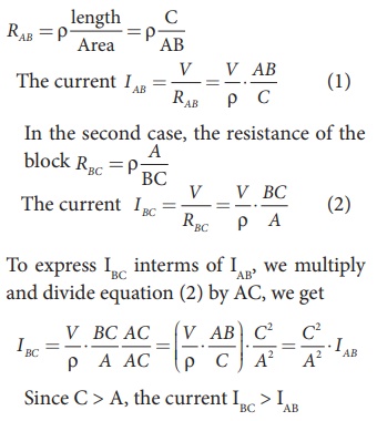
Solution
In the first case, the
resistance of the block
2.
Resistors in series and parallel
An electric circuit may
contain a number of resistors which can be connected in different ways. For
each type of circuit, we can calculate the equivalent resistance produced by a
group of individual resistors.
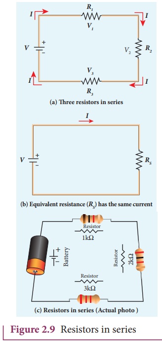
Resistors in series
When two or more
resistors are connected end to end, they are said to be in series. The
resistors could be simple resistors or bulbs or heating elements or other
devices. Figure 2.9 (a) shows three resistors R1, R2
and R3 connected in series.
The amount of charge
passing through resistor R1 must also pass through resistors R2
Due to this
reason, the current I passing through all the three resistors is the same.
According to OhmŌĆÖs law, if same current pass through different resistors of
different values, then the potential difference across each resistor must be
different. Let V1, V2 and V3
be the potential difference (voltage) across each of the resistors R1,
R2 and R3 respectively, then we can write V1
= IR1, V2 = IR2 and V3
= IR3. But the total voltage V is equal to the sum of
voltages across each resistor.
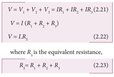
where RS is the equivalent resistance,
When several resistances
are connected in series, the total or equivalent resistance is the sum of the
individual resistances as shown in the Figure 2.9 (b).
Note: The value of equivalent
resistance in series connection will be greater than each individual
resistance.
EXAMPLE 2.8
Calculate the equivalent
resistance for the circuit which is connected to 24 V battery and also find the
potential difference across 4 ╬® and 6 ╬® resistors in the circuit.
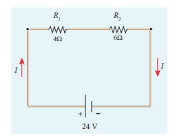
Solution
Since the resistors are connected in
series, the effective resistance in the circuit
= 4 ╬® + 6 ╬® = 10 ╬®
The Current I in the circuit= V/ Req
= 24/10 = 2 .4 A
Voltage across 4╬® resistor
V1 = IR1 = 2 .
4 A├Ś 4 ╬® = 9.6V
Voltage across 6 ╬® resistor
V2 = IR1 = 2 .
4 A├Ś 6 ╬® =14 .4V
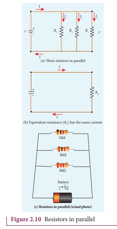
Resistors in parallel
Resistors are in
parallel when they are connected across the same potential difference as shown
in Figure 2.10 (a).
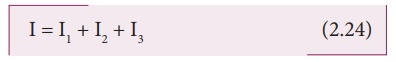
In this case, the total
current I that leaves the battery is split into three separate paths. Let I1,
I2 and I3 be the current through the resistors R1,
R2 and R3 respectively. Due to the conservation of
charge, total current in the circuit I is equal to sum of the currents through
each of the three resistors.
Since the voltage across
each resistor is the same, applying OhmŌĆÖs law to each resistor, we have
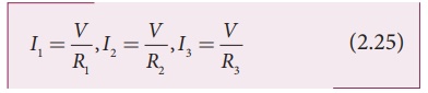
Substituting these
values in equation (2.24),we get
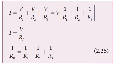
Here RP
is the equivalent resistance of the parallel combination of the resistors.
Thus, when a number of resistors are connected in parallel, the sum of the
reciprocal of the values of resistance of the individual resistor is equal to
the reciprocal of the effective resistance of the combination as shown in the
Figure 2.10 (b)
Note: The value of
equivalent resistance in parallel connection will be lesser than each
individual resistance.
House hold appliances
are always connected in parallel so that even if one is switched off, the other
devices could function properly.
EXAMPLE 2.9
Calculate the equivalent
resistance in the following circuit and also find the current I, I1
and I2 in the given circuit.
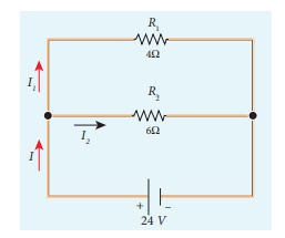
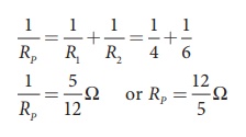
Solution
Since the resistances
are connected in parallel, therefore, the equivalent resistance in the circuit
is
The resistors are connected in parallel, the
potential (voltage) across each resistor is the same.
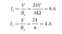
The current I is the
total of the currents in the two branches. Then,
I = I1 + I2=
6 A + 4 A = 10 A
EXAMPLE 2.10
When two resistances
connected in series and parallel their equivalent resistances are 15 ╬® and 56/15
╬® respectively. Find the individual resistances.
Solution
Rs = R1 + R2
= 15 ╬® (1)
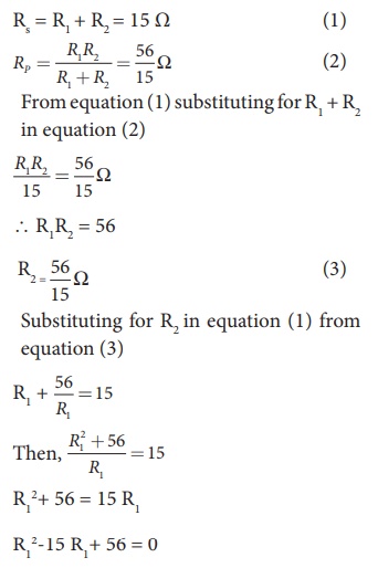
The above equation can
be solved using factorisation.
R12-8
R1-7 R1+ 56 = 0
R1 (R1ŌĆō
8) ŌĆō 7 (R1ŌĆō 8) = 0
(R1ŌĆō 8) (R1ŌĆō
7) = 0
If (R1= 8 ╬®)
using in equation (1)
8 + R2 = 15
R2 = 15 ŌĆō 8 =
7 ╬® ,
R2 = 7 ╬® i.e
, (when R1 = 8 ╬® ; R2 = 7 ╬®)
If (R1= 7 ╬®)
Substituting in equation
(1)
7 + R2 = 15
R2 = 8 ╬® , i.e , (when R1 = 8 ╬® ; R2 = 7 ╬® )
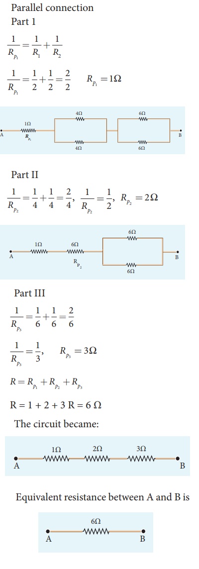
EXAMPLE 2.11
Calculate the equivalent
resistance between A and B in the given circuit.
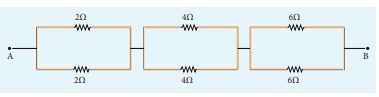
Solution
EXAMPLE 2.12
Five resistors are
connected in the configuration as shown in the figure. Calculate the equivalent
resistance between the points a and b.
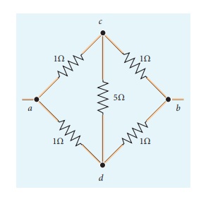
Solution
Case (a)
To find the equivalent
resistance between the points a and b, we assume that current is entering the
junction a. Since all the resistances in the outside loop are the same (1╬®),
the current in the branches ac and ad must be equal. So the electric potential
at the point c and d is the same hence no current flows into 5 ╬® resistance. It
implies that the 5 ╬® has no role in determining the equivalent resistance and
it can be removed. So the circuit is simplified as shown in the figure.
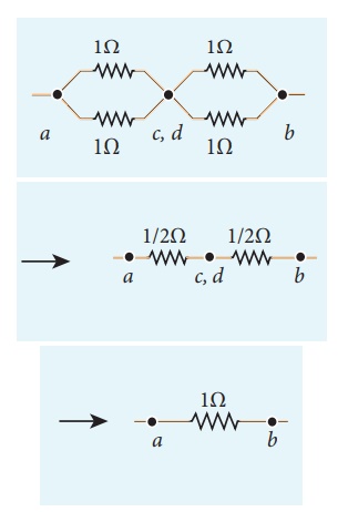
The equivalent resistance of the circuit between a and b is Req = 1╬®
3. Color code for Carbon resistors
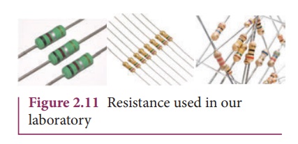
Carbon resistors
consists of a ceramic core, on which a thin layer of crystalline carbon is
deposited as shown in Figure 2.11. These resistors are inexpensive, stable and
compact in size. Color rings are used to indicate the value of the resistance
according to the rules given in the Table 2.2.
Three coloured rings are
used to indicate the values of a resistor: the first two rings are significant
figures of resistances, the third ring indicates the decimal multiplier after
them. The fourth color, silver or gold,
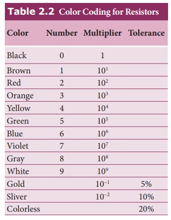
For the resistor shown
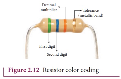
in Figure 2.12, the first digit = 5 (green), the second digit = 6
(blue), decimal multiplier = 103 (orange) and tolerance = 5% (gold). The value
of resistance = 56 ├Ś
103 Ōä” or 56 kŌä” with the tolerance
value 5%.
4. Temperature dependence of resistivity
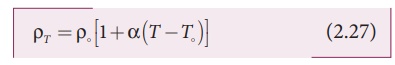
The resistivity of a
material is dependent on temperature. It is experimentally found that for a
wide range of temperatures, the resistivity of a conductor increases with
increase in temperature according to the expression,
where ŽüT is the resistivity of a
conductor at T oC, Žüo is the resistivity of the conductor at some reference temperature
T┬║ (usually at 20┬║C) and ╬▒ is the temperature coefficient
of resistivity. It is defined as the ratio of increase in resistivity
per degree rise in temperature to its resistivity at T┬║.
From the equation
(2.27), we can write
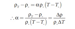
where ŌłåŽü = ŽüT ŌĆō Žüo is change in
resistivity for a change in temperature ŌłåT = T ŌĆō To. Its unit
is per oC.
╬▒ of conductors
For conductors ╬▒ is positive. If
the temperature of a conductor increases, the average kinetic energy of
electrons in the conductor increases. This results in more frequent collisions
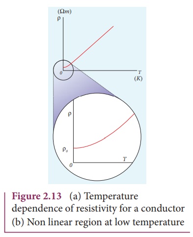
and hence the resistivity increases. The graph of the equation (2.27) is shown
in Figure 2.13
Even though, the
resistivity of conductors like metals varies linearly for wide range of
temperatures, there also exists a non-linear region at very low temperatures.
The resistivity approaches some finite value as the temperature approaches
absolute zero as shown in Figure 2.13(b).
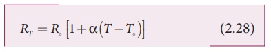
As the resistance is
directly proportional to resistivity of the material, we can also write the
resistance of a conductor at temperature T ┬║C as
The temperature
coefficient can be also be obtained from the equation (2.28),
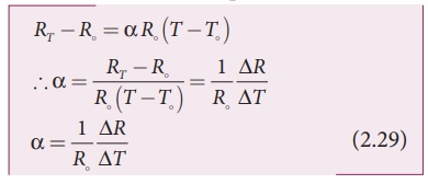
where R = RT ŌłÆR is change in
resistance during the change in temperature ╬öT = T ŌĆōT
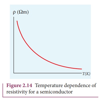
╬▒ of of semiconductors
For semiconductors, the
resistivity decreases with increase in temperature. As the temperature
increases, more electrons will be liberated from their atoms (Refer unit 9 for
conduction in semi conductors). Hence the current increases and therefore the
resistivity decreases as shown in Figure 2.14. A semiconductor with a negative
temperature coefficient of resistance is called a thermistor.
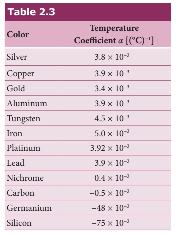
The typical values of temperature
coefficients of various materials are given in table 2.3.
We can understand the
temperature dependence of resistivity in the following way. In section 2.1.3,
we have shown thatthe electrical conductivity, Žā = ne2Žä / m . As the m resistivity
is inverse of Žā, it can be written as,
The resistivity of
materials is
i) inversely proportional to the number density
(n) of the electrons
ii) inversely proportional to the average time
between the collisions (Žä).
In metals, if the
temperature increases, the average time between the collision (Žä) decreases and
n is independent of temperature. In semiconductors when temperature increases,
n increases and Žä decreases, but increase in n is dominant than decreasing Žä,
so that overall resistivity decreases.
EXAMPLE 2.13
If the resistance of
coil is 3 ╬® at 20 0C and ╬▒ = 0.004/0C then determine its resistance at 100 0C.
Solution
R0= 3 ╬®,ŌĆā T =
100┬║C,ŌĆā T0 = 20┬║C
╬▒ = 0.004/┬║C,ŌĆā RT
= ?
RT= R0(1 +
╬▒(T-T0))
R100 = 3(1 +
0.004 ├Ś 80)
R100 = 3(1 +
0.32)
R100 =
3(1.32)
R100 = 3.96 ╬®
EXAMPLE 2.14
Resistance of a material
at 10┬║C and 40┬║C are 45 ╬® and 85 ╬® respectively. Find its temperature
co-efficient of resistance.
Solution
T0 = 10┬║C, T
= 40┬║C, R0= 45 ╬® , R = 85 ╬®
α = 1/R . ΔR /ΔT

╬▒ = 0.0296 per ┬║C
Related Topics