Explanation, Formulas, Solved Example Problems | KirchhoffŌĆÖs rule and WheatstoneŌĆÖs bridge - Comparison of emf of two cells with a potentiometer | 12th Physics : Current Electricity
Chapter: 12th Physics : Current Electricity
Comparison of emf of two cells with a potentiometer
Comparison of emf of two cells with a
potentiometer
To compare the emf of
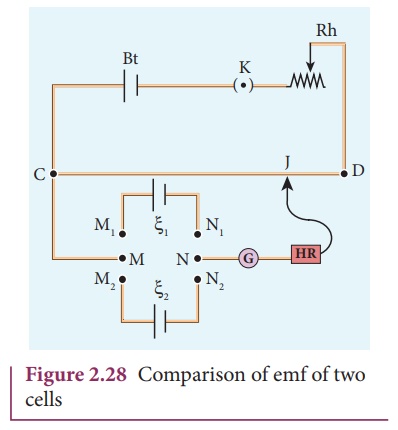
two cells, the circuit connections are made as shown in Figure 2.28.
Potentiometer wire CD is connected to a battery Bt and a key K in
series. This is the primary circuit. The end C of the wire is connected to the
terminal M of a DPDT (Double Pole Double Throw) switch and the other terminal N
is connected to a jockey through a galvanometer G and a high resistance HR. The
cells whose emf ╬Š1 and ╬Š2 to be compared are
connected to the terminals M1,N1
and M2,N2 of the DPDT switch. The positive terminals of Bt,
╬Š1 and ╬Š2 should be connected to
the same end C.

The DPDT switch is
pressed towards M1, N1 so that cell ╬Š 1 is included
in the secondary circuit and the balancing length l1 is found
by adjusting the jockey for zero deflection. Then the second cell ╬Š2 is included in the
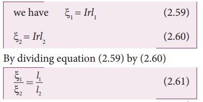
circuit and the balancing length l2 is determined. Let r
be the resistance per unit length of the potentiometer wire and I be the
current flowing through the wire.

By including a rheostat
(Rh) in the primary circuit, the experiment can be repeated several times by
changing the current flowing through it.
Related Topics