Explanation, Formulas, Solved Example Problems - Resistors in series and parallel | 12th Physics : Current Electricity
Chapter: 12th Physics : Current Electricity
Resistors in series and parallel
Resistors in series and parallel
An electric circuit may contain a number of resistors which can be connected in different ways. For each type of circuit, we can calculate the equivalent resistance produced by a group of individual resistors.
Resistors in series
When two or more resistors are connected end to end, they are said to be in series. The resistors could be simple resistors or bulbs or heating elements or other devices. Figure 2.9 (a) shows three resistors R1, R2 and R3 connected in series.
The amount of charge passing through resistor R1 must also pass through resistors R2
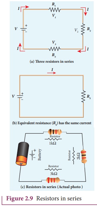
Due to this reason, the current I passing through all the three resistors is the same. According to OhmÔÇÖs law, if same current pass through different resistors of different values, then the potential difference across each resistor must be different. Let V1, V2 and V3 be the potential difference (voltage) across each of the resistors R1, R2 and R3 respectively, then we can write V1 = IR1, V2 = IR2 and V3 = IR3. But the total voltage V is equal to the sum of voltages across each resistor.
where RS is the equivalent resistance,
When several resistances are connected in series, the total or equivalent resistance is the sum of the individual resistances as shown in the Figure 2.9 (b).
Note: The value of equivalent resistance in series connection will be greater than each individual resistance.
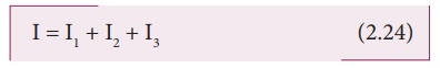
EXAMPLE 2.8
Calculate the equivalent resistance for the circuit which is connected to 24 V battery and also find the potential difference across 4 ╬ę and 6 ╬ę resistors in the circuit.
Solution
Since the resistors are connected in series, the effective resistance in the circuit
= 4 ╬ę + 6 ╬ę = 10 ╬ę
The Current I in the circuit= V/ Req = 24/10 = 2 .4 A
Voltage across 4╬ę resistor
V1 = IR1 = 2 . 4 A├Ś 4 ╬ę = 9.6V
Voltage across 6 ╬ę resistor
V2 = IR1 = 2 . 4 A├Ś 6 ╬ę =14 .4V
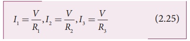
Resistors in parallel
Resistors are in parallel when they are connected across the same potential difference as shown in Figure 2.10 (a).
In this case, the total current I that leaves the battery is split into three separate paths. Let I1, I2 and I3 be the current through the resistors R1, R2 and R3 respectively. Due to the conservation of charge, total current in the circuit I is equal to sum of the currents through each of the three resistors.
Since the voltage across each resistor is the same, applying OhmÔÇÖs law to each resistor, we have
Substituting these values in equation (2.24),we get
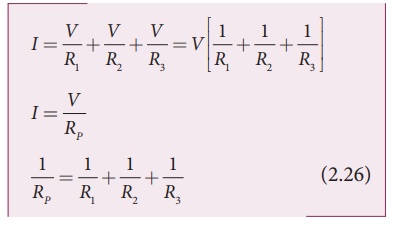
Here RP is the equivalent resistance of the parallel combination of the resistors. Thus, when a number of resistors are connected in parallel, the sum of the reciprocal of the values of resistance of the individual resistor is equal to the reciprocal of the effective resistance of the combination as shown in the Figure 2.10 (b)
Note: The value of equivalent resistance in parallel connection will be lesser than each individual resistance.
House hold appliances are always connected in parallel so that even if one is switched off, the other devices could function properly.
EXAMPLE 2.9
Calculate the equivalent resistance in the following circuit and also find the current I, I1 and I2 in the given circuit.
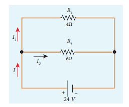
Solution
Since the resistances are connected in parallel, therefore, the equivalent resistance in the circuit is
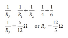
The resistors are connected in parallel, the potential (voltage) across each resistor is the same.
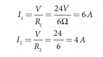
The current I is the total of the currents in the two branches. Then,
I = I1 + I2= 6 A + 4 A = 10 A
EXAMPLE 2.10
When two resistances connected in series and parallel their equivalent resistances are 15 ╬ę and 56/15 ╬ę respectively. Find the individual resistances.
Solution
Rs = R1 + R2 = 15 ╬ę (1)
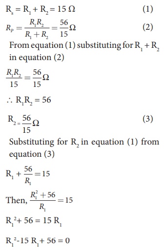
The above equation can be solved using factorisation.
R12-8 R1-7 R1+ 56 = 0
R1 (R1ÔÇô 8) ÔÇô 7 (R1ÔÇô 8) = 0
(R1ÔÇô 8) (R1ÔÇô 7) = 0
If (R1= 8 ╬ę)
using in equation (1)
8 + R2 = 15
R2 = 15 ÔÇô 8 = 7 ╬ę ,
R2 = 7 ╬ę i.e , (when R1 = 8 ╬ę ; R2 = 7 ╬ę)
If (R1= 7 ╬ę)
Substituting in equation (1)
7 + R2 = 15
R2 = 8 ╬ę , i.e , (when R1 = 8 ╬ę ; R2 = 7 ╬ę )
EXAMPLE 2.11
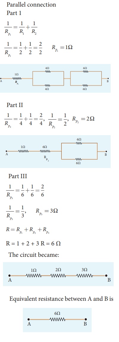
Calculate the equivalent resistance between A and B in the given circuit.
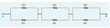
Solution
EXAMPLE 2.12
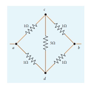
Five resistors are connected in the configuration as shown in the figure. Calculate the equivalent resistance between the points a and b.
Solution
Case (a)
To find the equivalent resistance between the points a and b, we assume that current is entering the junction a. Since all the resistances in the outside loop are the same (1╬ę), the current in the branches ac and ad must be equal. So the electric potential at the point c and d is the same hence no current flows into 5 ╬ę resistance. It implies that the 5 ╬ę has no role in determining the equivalent resistance and it can be removed. So the circuit is simplified as shown in the figure.
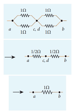
The equivalent resistance of the circuit between a and b is Req = 1╬ę
Related Topics