Chapter: Modern Analytical Chemistry: Chromatographic and Electrophoretic Methods
Electrophoresis: Instrumentation
Instrumentation
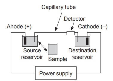
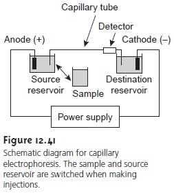
The basic instrumentation for capillary electrophoresis is shown in Figure 12.41
and includes a power supply for applying the electric field, anode and cathode compart- ments containing reservoirs of the buffer
solution, a sample
vial containing the sample, the capillary tube,
and a detector. Each part
of the instrument receives fur- ther consideration in this section.
Capillary Tubes
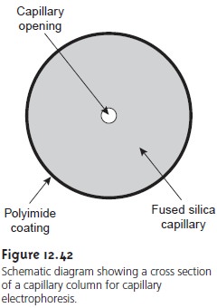
Figure 12.42 shows
a cross section
of a typical capillary tube.
Most capillary tubes are made from fused silica
coated with a 20ŌĆō35-╬╝m layer
of poly- imide to give it mechanical strength. The inner diameter
is typically 25ŌĆō75
╬╝m, which is smaller
than that for a capillary GC column, with an outer
diameter of200ŌĆō375 ╬╝m.
The narrow bore of the capillary column
and the relative
thickness of the capil-
laryŌĆÖs walls are important. When an electric
field is applied
to a capillary containing
a conductive medium, such as a buffer
solution, current flows
through the capillary. This current leads to Joule heating, the
extent of which
is proportional to the capil- laryŌĆÖs radius and the magnitude of the electric
field. Joule heating
is a problem be- cause it changes the
buffer solutionŌĆÖs viscosity, with the solution at the center
of the capillary being
less viscous than that near the capillary walls. Since the soluteŌĆÖs elec- trophoretic mobility depends on the bufferŌĆÖs
viscosity (see equation
12.36), solutes in the center of the capillary migrate at a faster rate than solutes
near the capillary walls. The result is additional band
broadening that degrades the separation. Capil- laries with smaller inner
diameters generate less
Joule heating, and
those with larger outer diameters are more effective at dissipating the heat. Capillary tubes may be placed inside a thermostated jacket to control
heating, in which
case smaller outer diameters allow a more rapid dissipation of thermal energy.
Injecting the Sample
The mechanism by which samples
are introduced in capil-
lary electrophoresis is quite different from that used in GC or HPLC.
Two types of injection are commonly used:
hydrodynamic injection and electrokinetic injec- tion. In both cases
the capillary tube
is filled with
buffer solution. One
end of the capillary tube is placed
in the destination reservoir, and the
other is placed
in the sample vial.
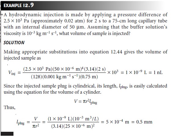
Hydrodynamic injection
uses pressure to force a small portion
of the sample into the capillary tubing. To inject
a sample hydrodynamically a difference in pres-
sure is applied across the capillary by either pressurizing the sample vial or by ap-
plying a vacuum to the destination reservoir. The volume of sample injected, in liters, is given
by the following equation
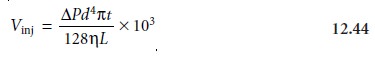
where ŌłåP is the
pressure difference across
the capillary in pascals, d is
the capillaryŌĆÖs inner diameter in meters,
t
is the amount of time that the pressure is applied
in sec- onds, ╬╝ is the buffer solutionŌĆÖs viscosity in kilograms
per meter per second (kg
mŌĆō1 sŌĆō1), and L is
the length of the capillary tubing in meters.
The factor of 103 changes the units from cubic meters to liters.
Electrokinetic injections are
made by placing
both the capillary and the anode into the sample vial and briefly
applying an electric
field. The moles
of solute in- jected into the capillary, ninj, are determined using
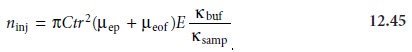
where C is the soluteŌĆÖs concentration in the sample,
t
is the amount of time that the electric field is applied,
r
is the capillaryŌĆÖs radius, ╬╝ep is the soluteŌĆÖs
electrophoretic mobility, ╬╝eof is the electroosmotic mobility, E is the applied electric
field, and ╬║buf and ╬║samp are the conductivities of the buffer solution and sample, respectively. An important consequence of equation 12.45
is that it is inherently biased toward sampling
solutes with larger
electrophoretic mobilities. Those
solutes with the largest
electrophoretic mobilities (smaller, more positively charged
ions) are injected
in greater numbers than those with the smallest electrophoretic
mobilities (smaller, more negatively charged
ions).
When a soluteŌĆÖs
concentration in the sample is too small to reliably
analyze, it may be possible to inject the solute in a manner that increases
its concentration in the
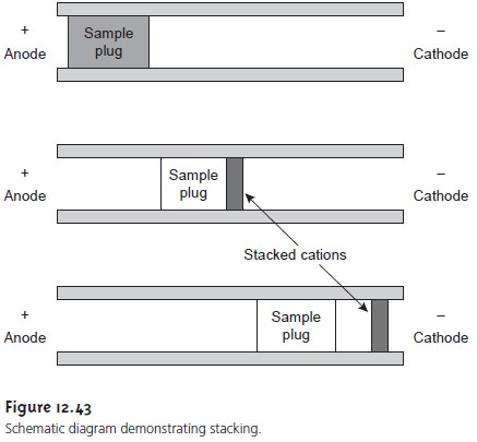
capillary tube. This method of injection is called stacking. Stacking is accom- plished by placing the sample in a solution
whose ionic strength
is significantly less than that of the buffering solution. Because the sample
plug has a lower concentra- tion of ions than the buffering
solution, its resistance is greater. Since the electric current passing through the
capillary is fixed,
we know from
OhmŌĆÖs law
E = iR
that the electric
field in the sample plug is greater
than that in the buffering solu- tion. Electrophoretic velocity
is directly proportional to the electric
field (see equation 12.35); thus, ions in the sample plug migrate with a greater
velocity. When the solutes reach the boundary between the sample
plug and the
buffering solution, the electric field decreases and their electrophoretic velocity slows down, ŌĆ£stackingŌĆØ to- gether in a smaller
sampling zone (Figure
12.43).
Applying the Electric Field
Migration in electrophoresis occurs in response to the applied electric field. The ability to apply a large electric field is important because higher voltages lead to shorter analysis times (see equation 12.41), more efficient separations (see equation 12.42), and better resolution (see equation 12.43). Be- cause narrow-bore capillary tubes dissipate Joule heating so efficiently, voltages of up to 40 kV can be applied.
Detectors
Most of the detectors used in HPLC
also find use
in capillary elec- trophoresis. Among
the more common
detectors are those
based on the absorption
of UV/Vis radiation, fluorescence, conductivity, amperometry, and mass
spectrom- etry. Whenever possible, detection is done
ŌĆ£on-columnŌĆØ before the
solutes elute from the
capillary tube and
additional band broadening occurs.
UV/Vis detectors are among the most popular.
Because absorbance is directly
proportional to path length, the capillary tubingŌĆÖs
small diameter leads to signals that are smaller than
those obtained in HPLC. Several
approaches have been
used to increase the path
length, including a Z-shaped sample cell or multiple reflections (Figure 12.44). Detection
limits are about 10ŌĆō7 M.

Better detection limits
are obtained using
fluorescence, particularly when
using a laser as an excitation source. When using
fluorescence detection, a small portion of the capillaryŌĆÖs protective coating is removed
and the laser
beam is focused
on the inner portion
of the capillary tubing. Emission
is measured at an angle
of 90┬░ to the laser. Because
the laser provides
an intense source of radiation
that can be focused
to a
narrow spot, detection
limits are as low as 10ŌĆō16 M.
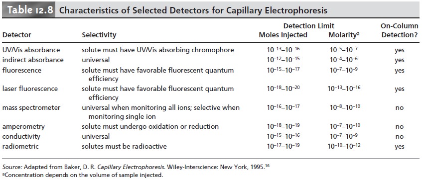
Solutes that do not absorb
UV/Vis radiation or undergo fluorescence can be detected by other detectors. Table 12.8 provides
a list of detectors used in capillary electrophoresis along
with some of their important characteristics.
Related Topics