Chapter: Embedded Systems
ARM processor
EMBEDDED PROCESSORS
Embedded processors can be broken into two broad categories: ordinary microprocessors (μP) and microcontrollers (μC), which have many more peripherals on chip, reducing cost and size.
Contrasting to the personal computer and server markets, a fairly large number of basic CPU architectures are used; there are Von Neumann as well as various degrees of Harvard architectures, RISC as well as non-RISC and VLIW; word lengths vary from 4-bit to 64-bits and beyond (mainly in DSP processors) although the most typical remain 8/16-bit. Most architecture comes in a large number of different variants and shapes, many of which are also manufactured by several different companies. e.g ARM
ARM PROCESSOR
The ARM
processor is widely used in cell phones and many other systems.
INTRODUCTION:
complex
instruction set computers (CISC).
These
machines provided a variety of instructions that may perform very complex
tasks, such as string searching; they also generally used a number of different
instruction formats of varying lengths.
Reduced
instruction set computers (RISC)
These
computers tended to provide somewhat fewer and simpler instructions it.
Streaming
data.
Data sets
that arrive continuously and periodically are called Streaming data.
Assembly language:
Assembly
language has the following features:
One instruction appears per line.
Labels,
which give names to memory locations, start in the first column.
Instructions
must start in the second column or after to distinguish them from labels.
Comments
run from some designated comment character (; in the case of ARM) to the end of the line
Assemblers
must also provide some pseudo-ops to help programmers
create complete assembly language programs.An example of a pseudo-op is one
that allows data values to be loaded into memory locations.These allow
constants,for example, to be set into memory. TheARM % pseudo-op allocates a
block of memory of the size specified by the operand and initializes locations
to zero.
e.g)
label1
ADR r4,c
LDR
r0,[r4] ; a comment ADR r4,d LDR r1,[r4]
SUB
r0,r0,r1 ; another comment
ARM PROCESSOR:
ARM is
actually a family of RISC architectures that have been developed over many
years. ARM does not manufacture its own VLSI devices; rather, it licenses its
architecture to companies who either manufacture the CPU itself or integrate
the ARM processor into a larger system.
The
textual description of instructions, as opposed to their binary representation,
is called an assembly language. ARM instructions are written one per line,
starting after the first column. Comments begin with a semicolon and continue
to the end of the line. A label, which gives a name to a memory location, comes
at the beginning of the line, starting in the first column
e.g) LDR
r0,[r8]; a comment label ADD r4,r0,r1
1. Processor
and Memory Organization
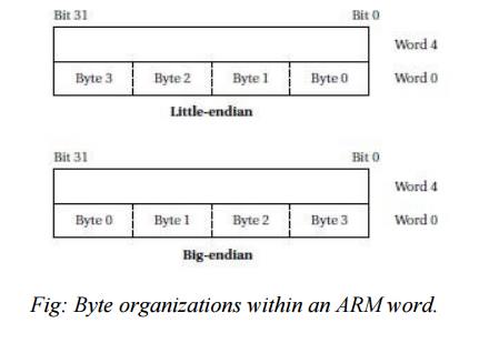
TheARM
architecture supports two basic types of data:
ü
The standardARM word is 32 bits
long.
ü The word
may be divided into four 8-bit bytes
ARM7
allows addresses up to 32 bits long.An address refers to a byte,not a
word.Therefore, the word 0 in the ARM address space is at location 0, the word
1 is at 4, the word 2 is at 8,and so on.
The ARM
processor can be configured at power-up to address the bytes in a word in
either
ü
little-endian
mode
(with the lowest-order byte residing in the low-order bits of the word)
ü big-endian
mode (the
lowest-order byte stored in the highest bits of the word),
Data Operations:
Arithmetic
and logical operations in C are performed in variables. Variables are
implemented as memory locations.
Sample
fragment of C code with data declarations and several assignment statements.
The variables a, b, c, x, y,
and z all become data locations in
memory. In most cases data are kept relatively separate from instructions in
the program’s memory image. In the ARM processor, arithmetic and logical
operations cannot be performed directly on memory locations. While some
processors allow such operations to directly reference main memory,
ARM is a load-store
architecture—data operands must first be loaded into the CPU and then
stored back to main memory to save the results.
e.g)C
Fragment code
int a, b,
c, x, y, z; x_(a_b)_c; y_a*(b_c);
z_(a
<< 2) | (b & 15);
Following
Fig shows the registers in the basic ARM programming model. ARM has 16
general-purpose registers, r0 through r15. Except for r15, they are
identical—any operation that can be done on one of them can be done on the
other one also. The r15 register has the same capabilities as the other
registers, but it is also used as the program counter
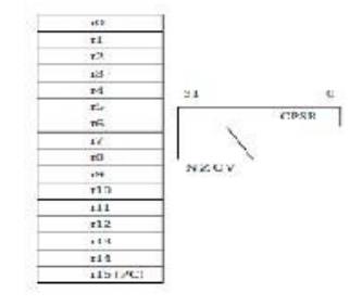
The other
important basic register in the programming model is the current program status
register (CPSR). This register is set automatically during every
arithmetic, logical, or shifting operation. The top four
bits of the CPSR hold the following useful information about the results of
that arithmetic/logical operation:
■ The
negative (N) bit is set when the result is negative in two’s-complement
arithmetic.
■ The zero
(Z) bit is set when every bit of the result is zero.
■ The carry
(C) bit is set when there is a carry out of the operation.
■ The
overflow(V) bit is set when an arithmetic operation results in an overflow.
Instruction
Sets in ARM
Following
figure summarizes the ARM move instructions. The instruction MOV r0, r1 sets
the value of r0 to the current value of r1. The MVN instruction complements the
operand bits (one’s complement) during the move.
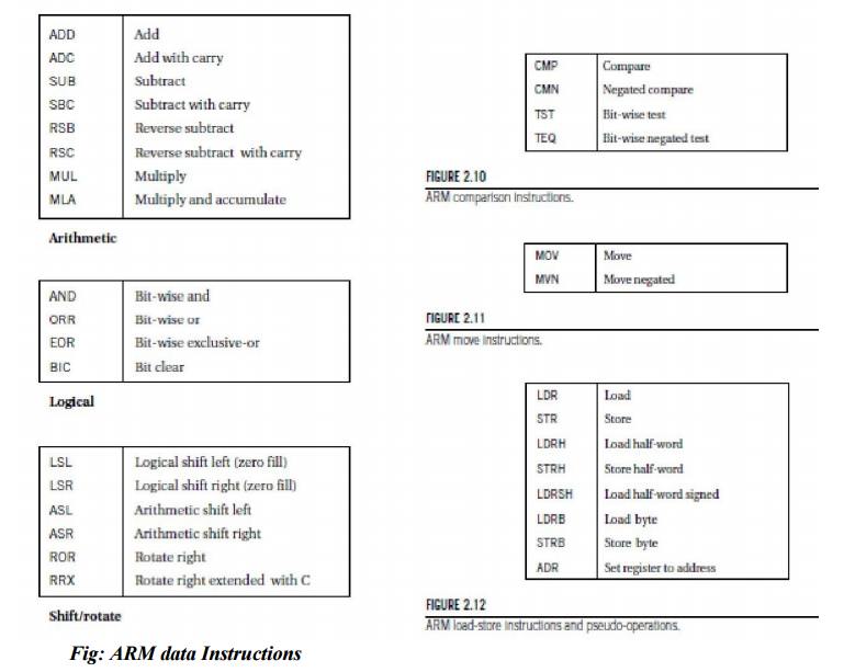
Fig: ARM
data Instructions
·
LDRB and STRB load and store bytes rather than
whole words,while LDRH and SDRH operate on half-words and LDRSH extends the
sign bit on loading.
· An ARM
address may be 32 bits long.
·
The ARM load and store instructions do not directly
refer to main memory addresses, since a 32-bit address would not fit into an
instruction that included an opcode and operands. Instead, the ARM uses register-indirect
addressing.
C
assignments in ARM instructions
We will
use the assignments of Figure 2.7. The semicolon (;) begins a comment after an
instruction, which continues to the end of that line. The statement
x = (a +b) _ c;
can be
implemented by using r0 for a, r1 for
b, r2 for c, and r3 for x . We also
need registers for indirect addressing. In this case, we will reuse the same
indirect addressing register, r4, for each variable load. The code must load
the values of a, b, and c into these
registers before performing the arithmetic, and it must store the value of x back to memory when it is done. This
code performs the following necessary steps:
ADR r4,a
; get address for a LDR r0,[r4] ; get value of a
ADR r4,b
; get address for b, reusing r4 LDR r1,[r4] ; load value of b
ADD
r3,r0,r1 ; set intermediate result for x to a + b ADR r4,c ; get address for c
LDR
r2,[r4] ; get value of c
SUB
r3,r3,r2 ; complete computation of x ADR r4,x ; get address for x
STR
r3,[r4] ; store x at proper location
Flow of Control
The B
(branch) instruction is the basic mechanism in ARM for changing the flow of
control. The address that is the destination of the branch is often called the branch
target.
Branches
are PC-relative—the
branch specifies the offset from the current PC value to the branch target.
The
offset is in words, but because the ARM is byte addressable, the offset is
multiplied by four (shifted left two bits, actually) to form a byte address.
Thus, the
instruction B #100
will add
400 to the current PC value.
Implementing an if statement in ARM
We will
use the following if statement as an example: if (a < b)
{
x = 5;
y = c +
d;
}
else x =
c – d;
The
implementation uses two blocks of code, one for the true case and another for
the false case. A branch may either fall through to the true case or branch to
the false case:
compute and test the condition ADR r4,a ; get
address for a LDR r0,[r4] ; get value of a ADR r4,b ; get address for b LDR
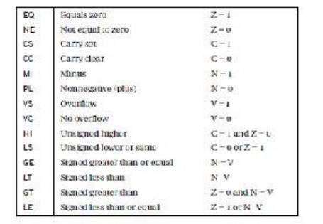
r1,[r4] ; get value of b CMP r0, r1 ; compare a < b
BGE
fblock ; if a >= b, take branch the true block follows
MOV r0,#5
; generate value for x
ADR r4,x
; get address for x
STR
r0,[r4] ; store value of x ADR r4,c ; get address for c
LDR
r0,[r4] ; get value of c ADR r4,d ; get address for d LDR r1,[r4] ; get value
of d ADD r0,r0,r1 ; compute c + d ADR r4,y ; get address for y STR r0,[r4] ;
store value of y
B after ;
branch around the false block ; the false block follows
fblock
ADR r4,c ; get address for c LDR r0,[r4] ; get value of c ADR r4,d ; get
address for d LDR r1,[r4] ; get value of d SUB r0,r0,r1 ; compute c – d ADR
r4,x ; get address for x STR r0,[r4] ; store value of x after ... ; code after
the if statement
Related Topics