Chapter: Embedded Systems Design : Embedded processors
The ARM RISC architecture
The ARM RISC architecture
It is probably fair to say that the ARM RISC architecture is really what
RISC is all about. Small simple processors that provide adequate performance
for their intended marketplace. For ARM, this was not the area of blinding
performance but in the then embryonic mobile and handheld world where power
consump-tion is as important as anything else. ARM also brought in the concept
of the fabless semiconductor company where they licence their designs to others
to build. As a result, if you want an ARM processor then you need to go to one
of the 50+ licenced manufac-turers. As a result, ARM processor architectures
power the bulk of the digital mobile phones and organisers available today.
The ARM register set
The architecture uses standard RISC architecture techniques (load-store
architecture, simple addressing modes based on regis-ter contents and
instruction information only, fixed length in-structions etc.,) and has a large
32 register file which is banked to provide a programming model of 16 registers
with additional registers from the 32 used when the processor handles exceptions.
This is called register banking where some of the spare registers are allocated
as replacements for a selected set of the first 16 registers. This means that
there is little need to save the registers during a context switch. This
mechanism is very similar to register windowing in reality.
Two registers have special usage: register 14 is used as a link register
and holds the address of the next instruction after a branch and link
instruction. This permits the software flow to return using this link address
after a subroutine has been executed. While it can be used as a general purpose
register, care has to be taken that its contents are not destroyed so that when
a return is executed, the program returns to the wrong address or even one that
has no associated memory! Register 15 is used as the program counter. The ARM
architecture uses a fixed 4 byte instruction word and supports the aligned
instruction organisation only. This means that each instruction must start on a
word boundary and also means that the lowest two bits in the program counter
are always set to zero. In effect, this reduces the register to only 30 bits is
size. Looking at the PC can be a little strange as it points not to the
currently executing instruction but to two instructions after that. Useful to
remember when debugging code.
While registers 14 and 15 are already allocated to special use, the
remaining 14 registers may also be used for special functions. These
definitions are not forced in hardware as is the case with the previous two
examples, but are often enforced in software either through the use of a
programming convention or by a compiler. Register 13 is frequently used as a
stack pointer by convention but other registers could be used to fulfil this
function or to provide additional stack pointers.
Exceptions
Exception processing with the ARM architecture is a little more
complicated in that it supports several different exception processing modes
and while it could be argued that these are nothing more than a user mode and
several variants of a supervi-sor mode (like many other RISC architectures),
they are suffi-ciently different to warrant their separate status.
The processor normally operates in the user mode where it will execute
the bulk of any code. This gives access to the 16 register program file as
previously described. To get into an exception mode from a user mode, there are
only five methods to do so. The common methods such as an interrupt, a software
interrupt, memory abort and the execution of an undefined in-struction are all
there. However a fifth is supported which is designed to reduce the latency
time taken to process a fast inter-rupt. In all cases, the processor uses the
register banking to preserve context before switching modes. Registers 13 and
14 are both automatically banked to preserve their contents so that they do not
need to be saved. Once in the exception handler, register 14 is used to hold
the return address ready for when the handler completes and returns and
register 13 provides a unique stack pointer for the handler to use. Each
exception will cause the current instruction to complete and then the execution
flow will change to the address stored in the associated location in the vector
table. This technique is similar to that used with both CISC and RISC
processors.
If the handler needs to use any of the other registers, they must be
saved before use and then restored before returning. To speed this process up,
there is a fifth mode called the fast interrupt mode where registers 8 to 12 are
also banked and these can be used by the handler without the overhead of saving
and restoring. This is known as the fast interrupt mode.
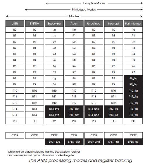
The exception modes do not stop there. There is also a sixth mode known
as the system mode which is effectively an enhanced user mode in that it uses
the user mode registers but is provided with privileged access to memory and
any coprocessors that might be present.
The Thumb instructions
The ARM processor architecture typically uses 32 bit wide instructions.
Now bearing in mind it is targeted at portable appli-cations where power
consumption is critical, the combination of RISC architectures coupled with 32
bit wide instructions leads to a characteristic known as code expansion. RISC
works by simpli-fying operations into several simple instructions. Each
instruction is 32 bits in size and a typical sequence may take three
instructions. This means that 12 bytes of program storage are needed to store
the instructions. Compare this to a CISC architecture that could do the same
work with one instruction with 6 bytes. This means that the RISC solution
requires twice as much program storage which means twice the memory cost and
power consumption (this is a bit of a simplification but the increase is very
significant). And yes, this argument is very similar to that put forward when
the first microprocessors appeared where memory was very expensive and it was
advantageous to uses as little of it as possible — hence the CISC
architectures.
ARM's solution to this was to add a new set of instructions to the
instructions set called the Thumb instructions. These are reduced in
functionality but are only 16 bits in size and therefore take less space. As
the processor always brings in data in 32 bit words, two Thumb instructions are
brought in and executed in turn. Thumb instructions are always executed in a
special Thumb mode which is controlled by a Thumb bit in the status register.
This requires some software support so that the compilers can insure that the
Thumb instruction sequences are only executed by the CPU when it is in its
Thumb mode, but the benefit is a greatly reduced code size, approaching that
offered by CISC processors.
Related Topics