Chapter: Embedded Systems Design : Embedded processors
INTEL 80386DX
INTEL 80386DX
The 80386 processor was introduced in 1987 as the first 32 bit member of
the family. It has 32 bit registers and both 32 bit data and address buses. It
is software compatible with the previous generations through the preservation
of the older register set within the 80386’s newer extended register model and
through a special 8086 emulation mode where the 80386 behaves like a very fast
8086. The processor has an on-chip paging memory manage-ment unit which can be
used to support multitasking and demand paging virtual memory schemes if
required.
Architecture
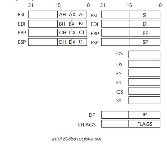
The 80386 has eight general-purpose 32 bit registers EAX, EBX, ECX, EDX,
ESI, EDI, EBP and ESP. These general-purpose registers are used for storing
either data or addresses. To ensure compatibility with the earlier 8086 processor,
the lower half of each register can be accessed as a 16-bit register (AX, BX,
CX, DX, SI, DI, BP and SP). The AX, BX, CX and DX registers can be also
accessed as 8 bit registers by changing the X suffix for either H or L thus
creating the 8088 registers AH, AL, BH, BL and so on.
To generate a 32 bit physical address, six segment registers (CS, SS,
DS, ES, FS, GS) are used with addresses from the general registers or
instruction pointer. The code segment (CS) is used with the instruction pointer
to create the addresses used for instruction fetches and any stack access uses
the SS register. The remaining segment registers are used for data addresses.
Each segment register has an associated descriptor register which is
used to program and control the on-chip memory man-agement unit. These
descriptor registers — controlled by the operating system and not normally
accessible to the application programmer — hold the base address, segment limit
and various attribute bits that describe the segment‘s properties.
The 80386 can run in three different modes: the real mode, where the
size of each segment is limited to 64 kbytes, just like the 8088 and 8086; a
protected mode, where the largest segment size is increased to 4 Gbytes; and a
special version of the protected mode that creates multiple virtual 8086
processor environments.
The 32 bit flag register contains the normal carry zero, auxiliary
carry, parity, sign and overflow flags. The resume flag is used with the trap 1
flag during debug operations to stop and start the processor. The remaining
flags are used for system control to select virtual mode, nested task operation
and input/output privilege level.
For external input and output, a separate peripheral ad-dress facility
is available similar to that found on the 8086. As an alternative, memory
mapping is also supported (like the M68000 family) where the peripheral is
located within the main memory map.
Interrupt facilities
The 80386 has two external interrupt signals which can be used to allow
external devices to interrupt the processor. The INTR input generates a
maskable interrupt while the NMI gener-ates a non-maskable interrupt and
naturally has the higher prior-ity of the two.
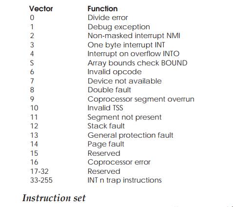
During an interrupt cycle, the processor carries out two interrupt
acknowledge bus cycles and reads an 8 bit vector number on D0–D7 during the
second cycle. This vector number is then used to locate, within the vector
table, the address of the corre-sponding interrupt service routine. The NMI
interrupt is auto-matically assigned the vector number of 2.
Software interrupts can be generated by executing the INT n instruction where n is the vector number for the
interrupt. The vector table consists of 4 byte
entries for each vector and starts at memory location 0 when the processor is
running in the real mode. In the protected mode, each vector is 8 bytes long.
The vector table is very similar to that of the 80286.
Vector Function
0 Divide error
1 Debug exception
2 Non-masked interrupt NMI
3 One byte interrupt INT
4 Interrupt on overflow INTO
S Array bounds check BOUND
6 Invalid opcode
7 Device not available
8 Double fault
9 Coprocessor segment
overrun
10 Invalid TSS
11 Segment not present
12 Stack fault
13 General protection fault
14 Page fault
15 Reserved
16 Coprocessor error
17-32 Reserved
33-255 INT n trap
instructions
Instruction set
The 80386 instruction set is essentially a superset of the 8086
instruction set. The format follows the dyadic approach and uses two operands
as sources with one of them also duplicating as a destination. Arithmetic and
other similar operations thus follow the A+B=B type of format (like the
M68000). When the processor is operating in the real mode — like an 8086
processor — its instruction set, data types and register model is essentially
re-stricted to a that of the 8086. In its protected mode, the full 80386
instruction set, data types and register model becomes available. Supported
data types include bits, bit fields, bytes, words (16 bits), long words (32
bits) and quad words (64 bits). Data can be signed or unsigned binary, packed
or unpacked BCD, character bytes and strings. In addition, there is a further
group of instructions that can be used when the CPU is running in protected
mode only. They provide access to the memory management and control registers.
Typically, they are not available to the user programmer and are left to the
operating system to use.
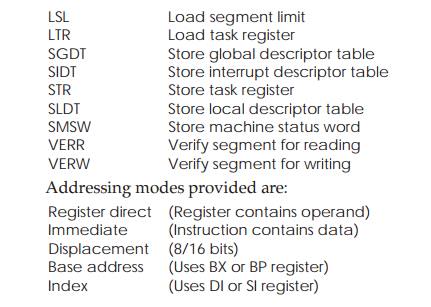
LSL Load segment limit
LTR Load task register
SGDT Store global descriptor
table
SIDT Store interrupt descriptor
table
STR Store task register
SLDT Store local
descriptor table
SMSW Store machine status
word
VERR Verify segment for
reading
VERW Verify segment for
writing
Addressing modes provided are:
Register direct (Register
contains operand)
Immediate (Instruction contains
data)
Displacement (8/16 bits)
Base address (Uses BX or BP
register)
Index (Uses DI or SI register)
80387 floating point coprocessor
The 80386 can also be used with the 80387 floating point coprocessor to
provide acceleration for floating point calculations. If the device is not
present, it is possible to emulate the floating point operations in software,
but at a far lower performance.
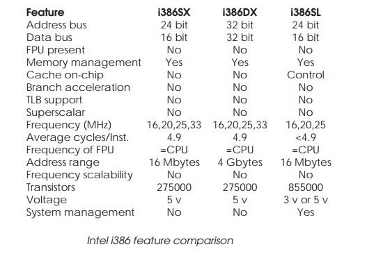
Feature comparison
There is a derivative of the 80386DX called the 80386SX which provides a
lower cost device while retaining the same architecture. To reduce the cost, it
uses an external 16 bit data bus and a 24 bit memory bus. The SX device is not
pin compatible with the DX device. These slight differences can cause quite
different levels of performance which can mean the difference between
performing a function of not.
In addition, Intel have produced an 80386SL device for portable PCs
which incorporates a power control module that provides support for efficient
power conservation.
Although Intel designed the 80386 series, the processor has been
successfully cloned by other manufacturers (both technically and legally) such
as AMD, SGS Thomson, and Cyrix. Their ver-sions are available at far higher
clock speeds than the Intel origi-nals and many PCs are now using them. These
are now available with all the peripherals needed to create a PC AT clone
integrated on the chip and these are extensively used to create embedded
systems based on the PC architecture.
Related Topics