Explanation, Formulas, Solved Example Problems | KirchhoffŌĆÖs rule and WheatstoneŌĆÖs bridge - Measurement of internal resistance of a cell by potentiometer | 12th Physics : Current Electricity
Chapter: 12th Physics : Current Electricity
Measurement of internal resistance of a cell by potentiometer
Measurement of internal resistance of a
cell by potentiometer
To measure the internal
resistance of a cell, the circuit connections are made as shown in Figure 2.29.
The end C of the potentiometer wire is connected to the positive terminal of
the battery Bt and the negative terminal of the battery is connected to the end
D through a key K1. This forms the primary circuit.
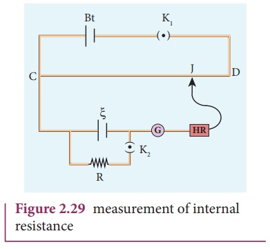
The positive terminal of
the cell ╬Š whose internal
resistance is to be determined is also connected to the end C of the wire. The
negative terminal of the cell ╬Š
is connected to a jockey through a galvanometer and a high resistance. A
resistance box R and key K2 are connected across the cell ╬Š. With K2
open, the balancing point J is obtained and the balancing length CJ = l1
is measured. Since the cell is in open circuit, its emf is
A suitable resistance
(say, 10 ╬®) is included in the resistance box and key K2 is closed.
Let r be the internal resistance of the cell. The current passing through the
cell and the resistance R is given by
I = ╬Š / [R +r]
The potential difference
across R is
V = ╬ŠR [R+r]
When this potential
difference is balanced on the potentiometer wire, let l2 be
the balancing length.
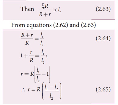
Substituting the values
of the R, l1 and l2 , the internal
resistance of the cell is determined. The experiment can be repeated for
different values of R. It is found that the internal resistance of the
cell is not constant but increases with increase of external resistance
connected across its terminals.
Related Topics