Chapter: Embedded Systems
Embedded Systems: Peripherals
EMBEDDED
SYSTEMS: PERIPHERALS
Chapter
Structure:
Objectives
1. Introduction
2. Testing Non Volatile Memory Devices
3. Control and Status Registers
4. Device Driver
5. Watchdog timer
OBJECTIVES
After reading this chapter you will learn:
Concept of testing non
–volatile memory devices using Checksum and CRC
Control and Status
Registers
Device Driver
Watch Dog Timer
1 INTRODUCTION
This chapter initially continues the part of
memory testing from last chapter. Here testing of Non Volatile memory devices
is studied.
Then we study how peripheral devices are
incorporated in Embedded System. Control and Status Registers, Device Drivers
and Watch Dog Timers are explained in the subsequent sections.
2 TESTING NON VOLATILE (ROM AND HYBRID) MEMORY
DEVICES
The testing techniques described previously
cannot help to test ROM and hybrid devices since ROM devices cannot be written
at all, and hybrid devices usually contain data or programs that cannot be
overwritten.
However ROM or hybrid memory device face the
same problems as missing memory chip, improperly inserted memory chip, damaged
memory chip or wiring problem with the memory chip.
Two Techniques Checksums and CRC can be used to
test non volatile memory devices.
Checksum
Checksums
basically deals with the question whether the data stored in a memory device is
valid or not?
To do this
the checksum of the data in the memory device is computed and stored along with
the data. The moment when we have to confirm the validity of the data, we just
have to recalculate the checksum and compare it with previous checksum. If the
two checksums match, the data is assumed to be valid.
The
simplest checksum algorithm is to add up all the data bytes discarding carries.
A Checksum
is usually stored at some fixed location in memory. This makes it easy to
compute and store the check sum for the very first time and later on to compare
the recomputed checksum with the original one.
Disadvantage:
A simple sum-of-data checksum cannot detect many of the most common data
errors.
CRC – Cyclic Redundancy Check
A Cyclic
Redundancy Check is a specific checksum algorithm designed to detect the most
common data errors.
CRC’s are
frequently used in Embedded Applications that requires the storage or
transmission of large blocks of data.
The CRC
works as follows:
The
message is composed of a long string of 0’s and 1’s
A division
operation occurs between the message at numerator and the generator polynomial
at denominator. The generator polynomial is a fixed smaller length binary
string.
The
remainder of the division operation is the CRC Checksum
3
CONTROL AND STATUS REGISTERS
Control and status
registers are the basic interface between and embedded processor and peripheral
device.
These registers are a
part of peripheral hardware and their location size and individual meanings are
feature of the peripheral.
For example, The
registers vary from device to device: example the registers within a serial
controller are very different from those in a timer.
Depending upon the
design of the processor and target board , peripheral devices are located
either in the processor’s memory space or within the I/O space.
It is common for
Embedded Systems to include some peripherals of each type. These are called
Memory-Mapped and I/O-mapped peripherals.
Of the two types,
memory-mapped peripherals are generally easier to work with and are
increasingly popular.
Memory-mapped control and
status registers can be used just like ordinary variables.
4
DEVICE DRIVER
The goal of designing a device driver is to hide
the hardware completely.
Attempts to hide the hardware completely are
difficult.
For example all Flash memory devices share the
concept of sectors. An erase operation can be performed only on an entire
sector. Once erased individual bites or words can be rewritten.
Device drivers for embedded systems are quite
different from the workstation counter parts. In modern computers workstation
device drivers are most often concerned with satisfying the requirement of the
operating system.
There are three benefits of good device driver:
Modularization, it
makes the structure of the overall software is easier to understand.
There exists only one
module that interacts directly with the peripheral’s registers making
communication easier.
Software changes that
result from hardware changes are localized to the device driver.
Components of a Device Driver
A device driver can be implemented (as
components) in the following steps:
A data structure that overlays the memory-mapped control and status
registers of the device:
This basic
step involves creating a C style structure that is actually a map of the
registers present in the device. These registers can be found out by referring
to the data sheet for the device.
A table is
created which maps the control register to their relative offsets.
An example
is shown below for a timer counter data structure.
struct TimerCounter
{
unsigned short count; // Current Count, offset 0x00 unsigned short maxCountA;// Maximum Count, offset 0x02 unsigned short _reserved; // Unused Space, offset 0x04 unsigned short control; // Control Bits, offset 0x06
};
To make the bits within the control register easier to read and write individually, we define the following bitmasks:
#define TIMER_ENABLE 0xC000 // Enable the timer.
#define TIMER_DISABLE 0x4000 // Disable the
timer.
#define TIMER_INTERRUPT 0x2000 // Enable timer
interrupts.
#define TIMER_MAXCOUNT 0x0020 // Timer complete?
#define TIMER_PERIODIC 0x0001 // Periodic timer?
A set of variables to track the current state of the hardware and device driver: It involves listing out the required variables needed to keep track of the state of the hardware and device driver
Initialize
the hardware: Once the
variables to be used are known the
next step in device driver programming is to initialize the hardware. Next
functions can be written to control the device.
A set
of routines that provide an API for users of the device driver
This involves writing different functions that
will implement the various tasks listed to be performed by the device.
Interrupt
service routines
Once the required functions and routines are
coded the thing remaining to be done is to identify and write routines for
servicing the interrupts.
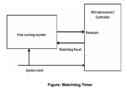
5 WATCHDOG
TIMER
It is
hardware equipment.
It is
special purpose hardware that protects the system from software hangs.
Watchdog
timer always counts down from some large number to zero
This
process takes a few seconds to reset, in the meantime, it is possible for
embedded software to “kick” the watchdog timer, to reset its counter to the
original large number.
If the
timer expires i.e. counter reaches zero, the watchdog timer will assume that
the system has entered a state of software hang, then resets the embedded
processor and restarts the software
It is a
common way to recover from unexpected software hangs
The figure below diagrammatically represents the
working of the watchdog timer
Related Topics