Chapter: 11th 12th std standard Class Physics sciense Higher secondary school College Notes
Television: Scanning and synchronising
Television: Scanning and synchronising
A still picture is fundamentally an arrangement
of many dark and light areas. Each small area of light or shade is called a
picture element. All the elements contain the visual information in the scene.
If they are transmitted and reproduced in the same degree of light or shade as
original and in proper position, the picture will be reproduced.
In order to produce video signal for all the
elements in the picture, it is scanned by the electron beam, one element at a
time, in sequential order. The scanning is done in the same way as a written
page is read to cover all the words in one line and all lines on the page.
Hence, scanning is the process by which an electron beam spot is made to move
across a rectangular area, so as to cover it completely. This rectangular area
may be the target surface in a television camera or the screen of a picture
tube in a television receiver.
The scene is scanned rapidly both in
the horizontal and vertical directions simultaneously. This provides sufficient
number of complete pictures or frames per second to give the illusion of
continuous motion. In most of the television systems, the frame repetition rate
(scanning frequency) is 25 per second.
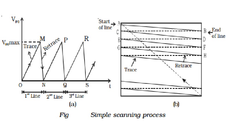
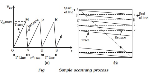
For scanning the picture elements, saw tooth potentials can
be used. Saw tooth potentials are produced by using a unijunction transistor
and a R-C network. Saw tooth potentials are applied to horizontal and vertical
deflector plates in a TV camera. When the saw tooth potential is applied to the
horizontal plates called line synchronising pulse, the electron beam at A
travels along a slanting line AB by the voltage variation of OM and reaches the
point B (Fig a and b). From B, the scanning spot travels along a line BC
by the voltage variation MN. In order that no picture should be scanned during
the return journey (i.e. the beam from the right horizontal end to the
beginning of the next line), a blanking pulse, which is a high negative
potential, is applied to the control grid of electron gun during the duration
of the return journey. This prevents the emission of electrons from electron
gun. Then the electron beam starts to scan the next line and the process gets
repeated till the whole picture is scanned. On reaching the right bottom
corner, the scanning spot quickly moves up to the top left corner by the
application of saw tooth potential to the vertical deflector plates, called
frame synchronising pulse. Thus for scanning the picture, the three
synchronising pulses are used. These synchronising pulses along with the output
of the TV camera are modulated on an ultra high frequency carrier and
transmitted. The accompanying sound is frequency modulated and transmitted via
the same antenna.
Interlaced scanning
In India, the frame repetition rate
has been standardised at 25 frames per second. This repetition rate is enough
to cause an illusion of continuity. But, the brightness of one frame blends
(mix) smoothly into the next, through this time when the screen is blanked
between successive frames. This results in definite flicker of light, that is
very annoying to the observer, when the screen becomes alternatively bright and
dark. To eliminate this flicker, each frame is scanned twice.
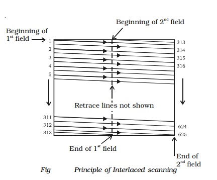
In this scanning, the total number lines are divided into
two groups called fields. During the presentation of the first field, only the
odd numbered lines are scanned, while during the second field all the even
numbered lines are scanned. Half way along the bottom of the first field, the
vertical retrace returns the scanning beam to the top of the image and
completes the unfinished lines. (i.e) The remaining even numbered lines are
then scanned during second field. This method of scanning is known as
interlaced scanning. In the 625 line TV system, for successful interlaced
scanning, the 625 lines of each frame or picture are divided into sets of 312.5
lines and each set is scanned alternatively to cover the entire picture area.
The principle of interlaced scanning is shown in Fig .
Hence, with the interlaced scanning
the flicker effect is eliminated without increasing the speed of scanning,
which in turn does not need any increase in channel bandwidth.
Horizontal and vertical scanning frequencies
The movement of electron beam spot from left to right and
back, so as to start a new line in the same direction is termed as horizontal
scanning. The horizontal scanning frequency is defined as the number of lines
scanned per second. In a 625 line system, transmitting 25 frames per second,
the horizontal frequency is 625 � 25 = 15,625 Hz.
Consequently, time taken to scan one line is 15,625 =
1/64 �s
Vertical scanning is the movement of the electron beam spot
in the vertical direction. One frame consists of two fields, resulting into 50
fields per second with a vertical field scan time of 1/50=20ms.
Related Topics