Chapter: 11th 12th std standard Class Physics sciense Higher secondary school College Notes
Radio reception: simple, AM and FM receiver
Radio reception
A radio receiver has the function of
selecting the desired signal from all other unwanted signals, amplifying,
demodulating it and finally producing it in the desired manner.
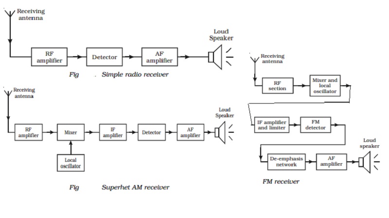
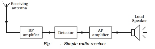
A simple (or) straight radio receiver
The functional block diagram of a simple radio receiver is
shown in Fig . The receiving antenna receives the radiowaves from different
broadcasting stations. The desired radiowave is selected by the radio frequency
amplifier, which employs a tuned parallel circuit. The tuned RF amplifier
amplifies this selected radiowave. The amplified radiowave is fed to the
detector circuit which consists of a PN diode. This circuit extracts the audio
signal from the radiowave. The output of the detector is the audio signal,
which is amplified by one or more stages of audio amplification. The amplified
audio signal is given to the loud speaker for sound reproduction.
Disadvantages
Simple radio
receiver circuit has
1.
poor sensitivity* and
2.
poor selectivity**
Superheterodyne AM receiver
The shortcomings of straight radio
receiver were overcome by the invention of superheterodyne receiver. All the
modern receivers utilise the superheterodyne circuit.
The functional block diagram of AM receiving system of
superheterodyne type is shown in Fig .
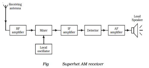
(i) RF amplifier
The RF amplifier uses a tuned
parallel circuit. The radiowaves from various broadcasting stations are
intercepted by the receiving antenna and are coupled to this stage. This stage
selects the desired radiowave and enhances the strength of the wave to the desired
level.
(ii) Mixer and local oscillator
The amplified output of RF amplifier
is fed to the mixer stage, where it is combined with the output of a local
oscillator. The two frequencies beat together and produce an intermediate
frequency (IF). The intermediate frequency is the difference between oscillator
frequency and radio frequency. The output of this section is always equal to
the intermediate frequency 455 kHz.
For example, if 600 kHz station is tuned, then local
oscillator will produce a frequency of 1055 kHz and consequently the output
from the mixer will have frequency of 455 kHz. By achieving this fixed
intermediate frequency, the amplifier circuit in such receivers can be made to
operate with maximum stability, selectivity and sensitivity.
(iii) IF amplifier
The output of the mixer circuit is
fed to the tuned IF amplifier. This amplifier is tuned to one frequency (i.e.
455 KHz ) and is amplified.
(iv) Detector
The output from the IF amplifier is
coupled with input of a detector. The audio signals are extracted from the IF
output. Usually a diode detector circuit is used because of its low distortion
and excellent audio fidelity (reproducing ability).
(v) AF amplifier
The detected AF signal is usually
weak and so it is further amplified by the AF amplifier. Then, the output
signal from the amplifier is fed to the loud speaker, which converts the audio
signal into sound waves corresponding to the original sound at the broadcasting
station.
FM Superheterodyne receiver
An FM receiver is a superheterodyne type like a typical AM
receiver. The functional block diagram of an FM receiver is shown in Fig .
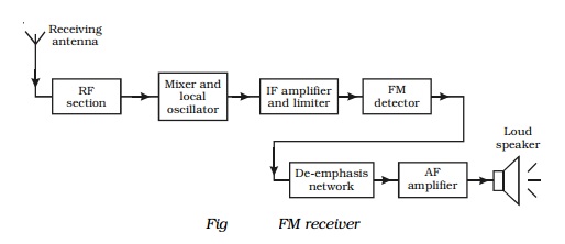
The RF section selects the incoming modulated signals and is
amplified. It is then fed into the mixer and local oscillator. Here the
frequency of the modulated signal is changed to intermediate frequency. For FM
receivers, this IF is 10.7 MHz. The intermediate frequency wave is amplified
using IF amplifier and then its amplitude is maintained constant using a
limiter*. The output of this section is applied to the FM detector which
demodulates the modulated wave. The AF signal from the FM detector is then
passed on through a de-emphasis network, where the various frequencies attain
their original power distribution. Finally it is fed into the loud speaker
after performing AF amplification.
Related Topics