Chapter: 11th 12th std standard Class Physics sciense Higher secondary school College Notes
Radio transmission - AM, FM transmitter and AF, RF section
Radio transmission
After modulation, the radio waves are
transmitted over long distances with the help of electronic circuits called
transmitters. The simplest form of transmitter consists of an oscillator,
generating a high frequency wave connected to an antenna. In this section, we
shall discuss the amplitude and frequency modulated transmitters.
Amplitude modulated (AM) transmitter
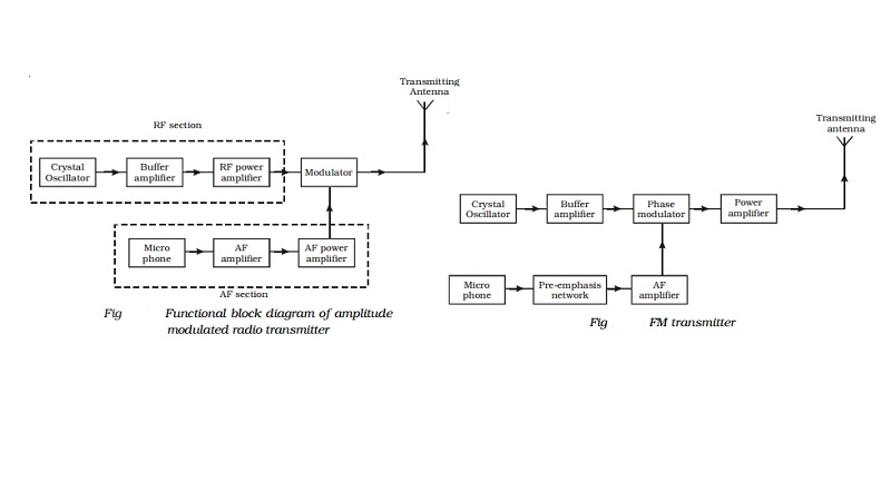
Fig gives the block diagram of amplitude
modulated radio transmitter. It consists of two sections (i) Audio frequency
(AF) section and (ii) Radio frequency (RF) section.
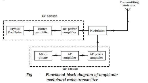
AF section
The AF section of the transmitter generates the modulating wave
(signal). The conversion of sound energy into electrical energy is performed by
the microphone.
The electrical energy available from the microphone
is very low. Hence, it is amplified through an amplifier. The output from the
AF amplifier is fed to the AF power amplifier. The power amplifier provides the
required audio frequency power. The output of the AF power amplifier is given
to the modulator. A modulator is an electronic circuit with transistor and
passive components, which performs the process of modulation.
RF section
In the RF section, the high frequency carrier wave is generated by
a crystal controlled oscillator. The output of the crystal controlled oscillator
is power amplified by RF power amplifier. The buffer* isolates the RF power
amplifier from the oscillator. This arrangement keeps the frequency of the
crystal controlled oscillator as a constant. In the modulator the RF wave and
modulating AF signal are mixed to produce the amplitude modulated wave. The
output of this section is fed to the antenna for transmission.
Frequency modulated (FM) transmitter
Frequency modulated systems are operated usually at a frequency
above 40 MHz. Frequency modulated broadcasting is done in television sound,
mobile radio etc. The functional block diagram of a FM transmitter employing
phase modulation is shown in Fig . The phase modulation is essentially a
frequency modulation.
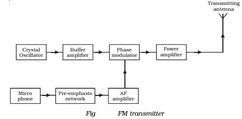
It consists of a crystal oscillator, which
produces the carrier wave and the output of this is fed into the phase
modulator. The buffer is a low frequency amplifier which isolates the crystal
oscillator from the phase modulator.
The modulating signal is produced from a microphone. Since this AF
modulating signal has uneven power, it is fed into a network called
pre-emphasis network, where all the frequencies in the modulating signal are
made to have equal power. The output of the pre-emphasis network is then
amplified and sent for phase modulation. The modulated output is then power
amplified using a power amplifier and then fed into the transmitting antenna
for transmission.
Related Topics