Chapter: Embedded Systems
Program for Embedded Systems and Build Process
PROGRAM
FOR EMBEDDED SYSTEMS AND BUILD PROCESS
Unit
Structure
Objectives
1. Introduction
2. Starting with Embedded Programming
3. “Hello World” For embedded systems
4. Blinking LED Program and Infinite loop
5. Build Process in Embedded System
OBJECTIVES
After reading this chapter you will be able to:
Know the difficulties
involved in programming embedded systems
Reasons for not
implementing Hello World as a first program
Write a generic code
for Blinking LED
Infinite loop
Build Process in
embedded system
1. INTRODUCTION
This chapter gives a head start into programming
the embedded system. The embedded code is just like any other code but there
are several restrictions. For Example: the code that runs on a computer makes
certain assumptions about the available memory while in embedded system there
is no scope for assumptions. The Embedded System Programmer has to know the
hardware before he can even attempt to write any code.
This chapter introduces to the readers the
Blinking LED program as a first program in embedded systems and explains why
the hello world would be rather a difficult program.
Then an essential necessity of the code is
explained: the infinite loop.
2. STARTING
WITH EMBEDDED PROGRAMMING
Programmers for Embedded systems must be
self-reliant. The usual built in functions (i.e. standard library routines like
cin and cout) may not be available to them.
Further, programmers for embedded systems have
to know beforehand what hardware is involved.
Example: They should know which processor will
be used, how much memory is available and what the memory offsets are. All this
information will change if the underlying hardware changes.
Embedded system programming has no scope for
assumption.
Example: Memory is a very limited hence precious
resource in an embedded system. A large amount of memory for code as well as
processing data would mean adding more memory to the circuit in the form of
additional memory. A simple variable declaration like an integer (usually 2
bytes or 4 bytes) should be thought carefully before declaring it. Declaring
the same variable as unsigned integer (1 byte) will suffice the purpose as well
as save memory location.
Not many programmers are available for
programming of embedded systems.
3. “HELLO
WORLD” FOR EMBEDDED SYSTEMS
Every book on programming language begins with
the example that prints "Hello, World!" on the output screen. The
hello world is a simple program that does not involve any logic and can be
implemented by a no-brainer (beginner).
However, in embedded systems, the hello world
program would be a bad choice to be implemented as a first program. In case of
any programming language the hello world program is executed on a general
purpose computer where we have requirements like CPU, input and output devices
and interaction between them taken care by the software and the operating
system.
In case of embedded system there may be no
operating system at all. Certain embedded systems may not even have an output
device like a monitor. Embedded systems usually have LED Displays. To
incorporate a display device in an embedded system the programmer would involve
writing a piece of code called a device
driver which otherwise is taken care by the operating system in case of a
general purpose computer.
Writing a code for a device driver is not an
easy job at beginner’s level. Hence hello world is a difficult program to begin
with while learning to program embedded system.
4. BLINKING LED PROGRAM AND INFINITE LOOP
The substitute for hello world program could be
a program that blinks an LED. LEDs are used in almost every embedded system.
Also the code used to program an LED would be very small.
To blink an LED we would require the following
hardware: o LED
o
A microcontroller or microprocessor
The LED can be connected to any available port
i.e P1, P2, P3, P4 on the microprocessor. Assuming the LED is connected to port
2, i.e. P2 its state is controlled by a bit in a register called the Port 2 I/O
Latch Register, also known the P2LTCH.
The structure of the program would be like this:
void main()
{
while (1)
{
toggle(LED_1); /* Change the state of the LED. */
delay(500); /* Pause for 500 milliseconds. */
}
}
The above
piece of code is hardware independent hence can be implemented for any circuit.
It
contains two functions namely : toggle() & delay()
otoggle(): This function is used to toggle the state of the LED.
delay(): This
function is used to introduce a delay of
500 ms every time the LED is toggled
The implementation of toggle() and delay() is
hardware specific.
Infinite
Loop
The code
for every embedded program is written in an infinite loop. This is because the
embedded system is supposed to run every time it is turned on till the time its
power goes off or it stops functioning.
The code
for blinking LED is also enclosed in an infinite loop. The functions toggle()
and delay() run infinite number of times.
An
application of an embedded system has an infinite loop around its code. It’s
just like the program you did to implement switch case where the program has to
run continuously until the user selects to exit.
5. BUILD PROCESS IN EMBEDDED SYSTEM
Definition: The
process which converts source code to executable
code is called as the build process.
The build process for embedded systems is
different. This is because the code to be run on an embedded system is written
one platform i.e. general purpose computer and executed on another platform
i.e. the target hardware.
An Embedded system would also use tools such as
a Compiler, Linker, Locater and Debugger to perform the entire build process.
These tools would be a part of a larger IDE.
A compiler which produces the executable code to
be run on a different platform is called a cross-compiler; else it is called a
native compiler.
Ex. Turbo C++ is a native compiler. The compiler
in case of embedded systems development is a cross compiler.
The build process involves three steps:
Compiling
Linking
Locating
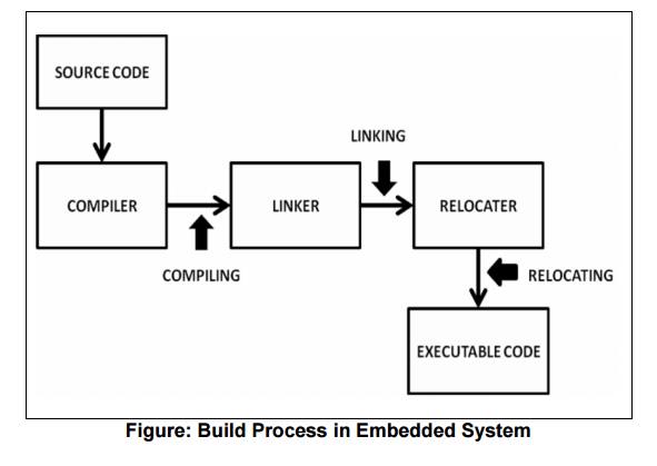
Compiling
o
The process of compiling is done by the
compiler.
o The compiler takes input as source code files and gives output as multiple object files.
o Compilers for embedded systems are essentially
cross-compilers. For example while compiling the programmer has to select the
target processor for which the code has to be generated.
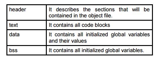
o The contents of the object files depend on its
format. Two commonly used formats are: 1. Common Object file
format (COFF)
2. Extended file format (ELF) o Object files generally have the following structure:
Linking
o
The process of linking is carried out by the
linker
o The linker takes input as multiple object files and gives output as a single object file which is also called as the relocatable
code.
The output of compiler is multiple object files.
These files are incomplete in the sense that they may contain reference to
variables and functions across multiple object files which need to be resolved.
The job of the linker is to combine these
multiple object files and resolve the unresolved symbols.
The Linker does this by merging the various
sections like text, data, and bss of the individual object files. The output of
the linker will be a single file which contains all of the machine language
code from all of the input object files that will be in the text section of
this new file, and all of the initialized and uninitialized variables will
reside in the new data section and bss section respectively.
Locating
The
process of relocating is carried out by the relocater.
The
relocater takes input as the relocatable code produced by the linker and gives
output as the final executable code.
This
output is a binary executable file which is called hex code.
The
locator needs to be given information about the memory available on the target
processor.
The
locator will use this information to assign physical memory addresses to each
of the code and data sections within the relocatable program code. Finally it
produces an output file that contains a binary memory image that can be loaded
into the target processors ROM.
Related Topics