Chapter: 11th 12th std standard Class Physics sciense Higher secondary school College Notes
Monochrome TV transmission
Monochrome TV transmission
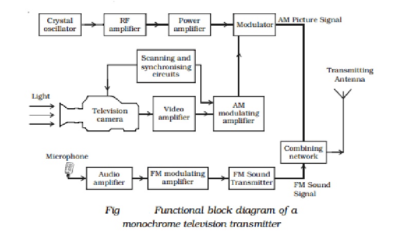
An over simplified block diagram of a monochrome TV transmitter is
shown in Fig . The functional block diagram can be broadly divided into
two sections, viz. an amplitude modulated transmitter and a frequency modulated
transmitter. Former is used for video modulation, whereas latter is used for
audio modulation.
The synchronising and scanning circuits produce
sets of pulses for providing synchronising pulses for proper functioning of the
TV system. This timing unit contains number of wave generating and wave shaping
circuits. The repetition rate of its various output pulse trains is controlled
by a frequency stabilised master oscillator.
The output signal of a camera tube
corresponding to the image to be televised is amplified through a number of
video amplifier stages.
The image signals together with the synchronising and blanking
pulses are raised to a level suitable for modulating the RF carrier wave
generated in the RF channel. The allotted picture carrier frequency is
generated by the crystal controlled oscillator. The continuous wave output is
given large amplification before feeding to the power amplifier. In the
modulator, its amplitude is made to vary in accordance with the modulating
signal received from the modulating amplifier.
The microphone converts the sound associated
with the picture being televised into proportionate electrical signal. The
audio signal from the microphone after amplification is frequency modulated,
employing the assigned carrier frequency. The output of the sound FM
transmitter is finally combined with the AM picture transmitter output, through
a combining network and fed to a common antenna for radiation of energy in the
form of electromagnetic waves.
Related Topics