Chapter: 11th 12th std standard Class Physics sciense Higher secondary school College Notes
Monochrome TV receiver

Monochrome TV receiver
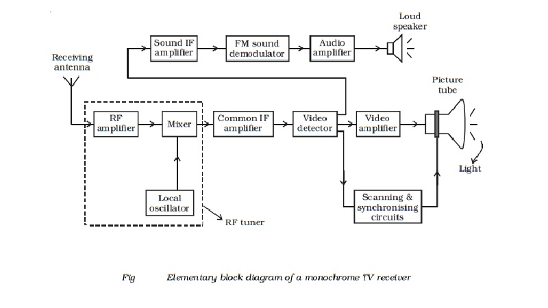
The simplified block diagram of a black and
white TV receiver is shown in Fig . The receiving antenna intercepts
radiated RF signals and the tuner selects the desired channel frequency band.
The antenna provides RF picture and sound signals for the RF amplifier stage.
The RF amplifier stage is then coupled into the mixer stage. The mixture is
connected to the local oscillator. The RF audio and video signals are
heterodyned into intermediate frequency by the mixer and local oscillator. The
RF amplifier, mixer and local oscillator stages are combinely called as the RF
tuner. The output signal from the tuner circuit is amplified by using a common
IF amplifier. Then the video and audio components are separated by a detector.
The sound signals are detected from FM waves, amplified and then fed into the
loud speaker, which reproduce the sound.
The video components are first passed into a detector which
separates the picture signal from the synchronising pulses. The line
synchronising pulses and the frame synchronising pulses are fed into the
horizontal and vertical deflector plates of the picture tube. The blanking
pulses are given to the control grid of the electron gun of the picture tube.
The picture signals are applied to the filament of the electron gun of the
picture tube. According to the variations of potential in the picture,
electrons are emitted from the electron gun. Thus, the intensity of the
fluorescent screen of the picture tube is in accordance with the variation of
potential in the picture and the picture is reproduced.
Related Topics