Chapter: Embedded Systems
Intruder Alarm System
CASE STUDY
Intruder Alarm System
In this
case study, we will consider the design and implementation of a small intruder
alarm system suitable for detecting
attempted thefts in a home or business environment Figure
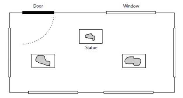
Figure shows
the same gallery with the alarm system installed. In this figure, each
of the windows has a sensor to detect
class breakage. A magnetic sensor is also attached to the door. In each case,
the sensors appear to be simple switches as far as the alarm system is
concerned. Foll fig also shows a ‘bell box’ outside the property: this will
sound if an intruder is detected
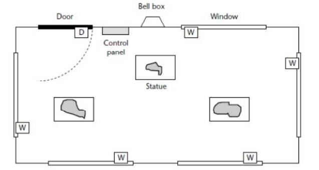
Inside
the door (in Figure 10.2), we have the alarm control panel: this consists
mainly of a small keypad, plus an additional ‘buzzer’ to indicate that the
alarm has sounded. The alarm system is
designed
in such a way that the user – having set the alarm by entering a four-digit
password – has time to open the door and leave the room before the monitoring
process starts. Similarly, if the user opens the door when the system is armed,
he or she will have time to enter the password before the alarm begins to
sound. When initially activated, the system is in ‘Disarmed’ state.
_ In
Disarmed state, the sensors are ignored. The alarm does not sound. The system
remains in this state until the user enters a valid password via the keypad (in
our demonstration system, the password is ‘1234’). When a valid password is
entered, the systems enters ‘Arming’ state.
_ In
Arming state, the system waits for 60 seconds, to allow the user to leave the
area before the monitoring process begins. After 60 seconds, the system enters
‘Armed’ state.
_ In
Armed state, the status of the various system sensors is monitored. If a window
sensor is tripped,31 the system enters ‘Intruder’ state. If the door sensor is
tripped, the system enters ‘Disarming’ state.
The
keypad activity is also monitored: if a correct password is typed in, the
system enters ‘Disarmed’ state.
_ In
Disarming state, we assume that the door has been opened by someone who may be
an authorized system user.
The
system remains in this state for up to 60 seconds, after which – by default –
it enters Intruder state. If, during the 60- second period, the user enters the
correct password, the system enters ‘Disarmed’ state.
_ In
Intruder state, an alarm will sound. The alarm will keep sounding
(indefinitely), until the correct password is entered
_ The
embedded operating system, sEOS,.
_ A
simple ‘keypad’ library, based on a bank of switches.This final system would
probably use at least 10 keys (see Figure 10.3): support for additional keys
can be easily added if required.
_ The
RS-232 library Running the program
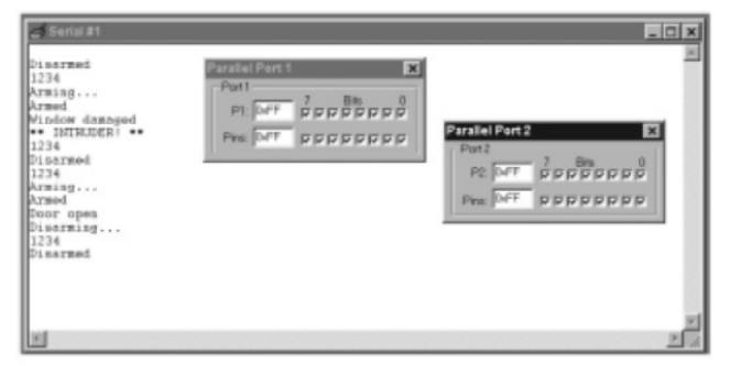
The
software
Part of
the intruder-alarm code
Part of
the intruder-alarm code (Main.C)
/*------------------------------------------------------------*-
Main.c
(v1.00)
-------------------------------------------------------------
Simple
intruder alarm system.
-*------------------------------------------------------------*/
#include
"Main.H"
#include
"Port.H"
#include
"Simple_EOS.H"
#include
"PC_O_T1.h"
#include
"Keypad.h"
#include
"Intruder.h"
/*
......................................................... */
void
main(void)
{
// Set
baud rate to 9600
PC_LINK_O_Init_T1(9600);
// Prepare
the keypad KEYPAD_Init();
// Prepare
the intruder alarm INTRUDER_Init();
// Set up
simple EOS (5ms tick) sEOS_Init_Timer2(5); while(1) // Super Loop
{
sEOS_Go_To_Sleep();
// Enter idle mode to save power
}
} Part of
the intruder-alarm code (Intruder.H)
/*------------------------------------------------------------*-
Intruder.H
(v1.00)
-------------------------------------------------------------
– See
Intruder.C for details.
-*------------------------------------------------------------*/
#include
"Main.H"
// ------
Public function prototypes --------------------------
void
INTRUDER_Init(void); void INTRUDER_Update(void);
/*------------------------------------------------------------*-
Part of
the intruder-alarm code (Intruder.C)
/*------------------------------------------------------------*-
Intruder.C
(v1.00)
-------------------------------------------------------------
Multi-state
framework for intruder alarm system.
-*------------------------------------------------------------*/
#include
"Main.H"
#include
"Port.H" #include "Intruder.H" #include
"Keypad.h" #include "PC_O.h"
// ------
Private data type declarations ----------------------
Possible
system states
typedef
enum
{DISARMED,
ARMING, ARMED, DISARMING, INTRUDER} eSystem_state;
// ------
Private function prototypes -------------------------
bit
INTRUDER_Get_Password_G(void);
bit
INTRUDER_Check_Window_Sensors(void); bit INTRUDER_Check_Door_Sensor(void); void
INTRUDER_Sound_Alarm(void);
// ------
Private variables -------------
void
INTRUDER_Init(void)
{
// Set the
initial system state (DISARMED) System_state_G = DISARMED;
// Set the
'time in state' variable to 0
State_call_count_G
= 0;
// Clear the
keypad buffer KEYPAD_Clear_Buffer();
// Set the
'New state' flag New_state_G = 1;
// Set the
(two) sensor pins to 'read' mode Window_sensor_pin = 1;
Sounder_pin
= 1;
}
/*
--------------------------------------------------------- */ void
INTRUDER_Update(void)
{
// Incremented
every time
if
(State_call_count_G < 65534)
{
State_call_count_G++;
}
// Call
every 50 ms switch (System_state_G)
{
case
DISARMED:
{
if
(New_state_G)
{
PC_LINK_O_Write_String_To_Buffer("\nDisarmed");
New_state_G = 0;
}
// Make sure
alarm is switched off
Sounder_pin
= 1;
// Wait
for correct password ...
if
(INTRUDER_Get_Password_G() == 1)
{
System_state_G
= ARMING;
New_state_G
= 1;
State_call_count_G
= 0;
break;
}
break;
}
case
ARMING:
{
if
(New_state_G)
{
PC_LINK_O_Write_String_To_Buffer("\nArming...");
New_state_G
= 0;
}
// Remain
here for 60 seconds (50 ms tick assumed)
if
(++State_call_count_G > 1200)
{
System_state_G
= ARMED;
New_state_G
= 1;
State_call_count_G
= 0;
break;
}
break;
}
case
ARMED:
{
if
(New_state_G)
{
PC_LINK_O_Write_String_To_Buffer("\nArmed");
New_state_G
= 0;
}
// First,
check the window sensors
if
(INTRUDER_Check_Window_Sensors() == 1)
{
// An
intruder detected
System_state_G
= INTRUDER;
New_state_G
= 1;
State_call_count_G
= 0;
break;
}
// Next,
check the door sensors
if
(INTRUDER_Check_Door_Sensor() == 1)
{
// May be
authorised user – go to 'Disarming' state
System_state_G
= DISARMING;
New_state_G
= 1;
State_call_count_G
= 0;
break;
}
//
Finally, check for correct password
if
(INTRUDER_Get_Password_G() == 1)
{
System_state_G
= DISARMED;
New_state_G
= 1;
State_call_count_G
= 0;
break;
}
break;
}
case
DISARMING:
{
if
(New_state_G)
{
PC_LINK_O_Write_String_To_Buffer("\nDisarming...");
New_state_G
= 0;
}
// Remain
here for 60 seconds (50 ms tick assumed)
// to
allow user to enter the password
// –
after time up, sound alarm
if
(++State_call_count_G > 1200)
{
System_state_G
= INTRUDER;
New_state_G
= 1;
State_call_count_G
= 0;
break;
}
// Still
need to check the window sensors
if
(INTRUDER_Check_Window_Sensors() == 1)
{
// An
intruder detected
System_state_G
= INTRUDER;
New_state_G
= 1;
State_call_count_G
= 0;
break;
}
//
Finally, check for correct password
if
(INTRUDER_Get_Password_G() == 1)
{
System_state_G
= DISARMED;
New_state_G
= 1;
State_call_count_G
= 0;
break;
}
break;
}
case
INTRUDER:
{
if
(New_state_G)
{
PC_LINK_O_Write_String_To_Buffer("\n**
INTRUDER! **"); New_state_G = 0;
}
// Sound
the alarm! INTRUDER_Sound_Alarm();
// Keep
sounding alarm until we get correct password if (INTRUDER_Get_Password_G() ==
1)
{
System_state_G
= DISARMED;
New_state_G
= 1;
State_call_count_G
= 0;
}
break;
} } }
/*
--------------------------------------------------------- */
bit
INTRUDER_Get_Password_G(void)
{
signed
char Key;
tByte
Password_G_count = 0;
tByte i;
// Update
the keypad buffer KEYPAD_Update();
// Are there
any new data in the keypad buffer?
if
(KEYPAD_Get_Data_From_Buffer(&Key) == 0)
{
// No new
data – password can’t be correct return 0;
}
// If we are
here, a key has been pressed
// How long
since last key was pressed?
// Must be
pressed within 50 seconds (assume 50 ms 'tick') if (State_call_count_G >
1000)
{
// More than
50 seconds since last key
// – restart
the input process
State_call_count_G
= 0; Position_G = 0;
}
if
(Position_G == 0)
{
PC_LINK_O_Write_Char_To_Buffer('\n');
}
PC_LINK_O_Write_Char_To_Buffer(Key);
Input_G[Position_G]
= Key;
// Have
we got four numbers?
if
((++Position_G) == 4)
{
Position_G
= 0;
Password_G_count
= 0;
// Check
the password
for (i =
0; i < 4; i++)
{
if
(Input_G[i] == Password_G[i])
{
Password_G_count++;
} } }
if
(Password_G_count == 4)
{
// Password
correct return 1;
}
else
{
// Password
NOT correct
return 0;
}
} /* ---
bit
INTRUDER_Check_Door_Sensor(void)
{
// Single
door sensor (access route) if (Door_sensor_pin == 0)
{
// Someone
has opened the door...
PC_LINK_O_Write_String_To_Buffer(’\nDoor
open’);
return 1;
}
//
Default
return 0;
}
/*
--------------------------------------------------------- */
void
INTRUDER_Sound_Alarm(void)
{
if
(Alarm_bit)
{
// Alarm
connected to this pin
Sounder_pin
= 0;
Alarm_bit
= 0;
}
else
{
Sounder_pin
= 1;
Alarm_bit
= 1;
}
}
/*------------------------------------------------------------*-
---- END
OF FILE ---------------------------------------------*-
Figure
shows one possible organization for an embedded system.
An
embedded system encompasses the CPU as well as many other resources.
In
addition to the CPU and memory hierarchy, there are a variety of interfaces
that enable the system to measure, manipulate, and otherwise interact with the
external environment. Some differences with desktop computing may be:
The human
interface may be as simple as a flashing light or as complicated as real-time
robotic vision.
The
diagnostic port may be used for diagnosing the system that is being controlled
-- not just for diagnosing the computer.
Special-purpose
field programmable (FPGA), application specific (ASIC), or even non-digital
hardware may be used to increase performance or safety.
Software
often has a fixed function, and is specific to the application.
In addition to the emphasis on interaction with the external world,
embedded systems also provide functionality specific to their applications.
Instead of executing spreadsheets, word processing and engineering analysis, embedded
systems typically execute control laws, finite state machines, and signal
processing algorithms. They must often detect and react to faults in both the
computing and surrounding electromechanical systems, and must manipulate
application-specific user interface devices.
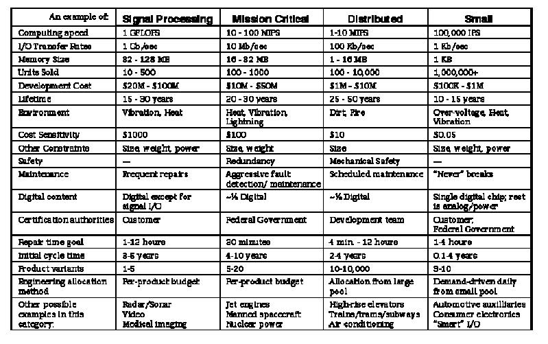
Table 1.
Four example embedded systems with approximate attributes.
In order
to make the discussion more concrete, we shall discuss four example systems
(Table 1). Each example portrays a real system in current production, but has
been slightly genericized to represent a broader cross-section of applications
as well as protect proprietary interests. The four examples are a Signal
Processing system, a Mission Critical control system, a Distributed control
system, and a Small consumer electronic system. The Signal Processing and
Mission Critical systems are representative of traditional military/aerospace
embedded systems, but in fact are becoming more applicable to general
commercial applications over time.
Using
these four examples to illustrate points, the following sections describe the
different areas of concern for embedded system design: computer design,
system-level design, life-cycle support, business model support, and design
culture adaptation.
Desktop computing design methodology and tool support is to a large
degree concerned with initial design of the digital system itself. To be sure,
experienced designers are cognizant of other aspects, but with the recent
emphasis on quantitative design
life-cycle issues that aren't readily quantified could be left out of
the optimization process. However, such an approach is insufficient to create
embedded systems that can effectively
compete in the marketplace. This is because in many cases the issue is not
whether design of an immensely complex system is feasible, but rather whether a
relatively modest system can be highly optimized for life-cycle cost and
effectiveness.
While
traditional digital design CAD tools can make a computer designer more
efficient, they may not deal with the central issue -- embedded design is about
the system, not about the computer. In desktop computing, design often focuses
on building the fastest CPU, then supporting it as required for maximum
computing speed. In embedded systems the combination of the external interfaces
(sensors, actuators) and the control or sequencing algorithms is or primary
importance. The CPU simply exists as a way to implement those functions. The
following experiment should serve to illustrate this point: ask a roomful of
people what kind of CPU is in the personal computer or workstation they use.
Then ask the same people which CPU is used for the engine controller in their
car (and whether the CPU type influenced the purchasing decision).
In
high-end embedded systems, the tools used for desktop computer design are
invaluable. However, many embedded systems both large and small must meet
additional requirements that are beyond the scope of what is typically handled
by design automation. These additional needs fall into the categories of
special computer design requirements, system-level requirements, life-cycle
support issues, business model compatibility, and design culture issues.
LIFE-CYCLE SUPPORT
Figure
shows one view of a product life-cycle.
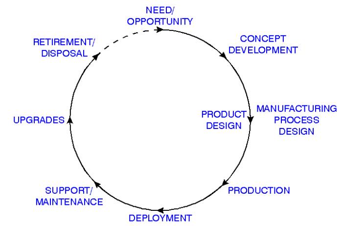
First a
need or opportunity to deploy new technology is identified. Then a product
concept is developed. This is followed by concurrent product and manufacturing
process design, production, and deployment. But in many embedded systems, the
designer must see past deployment and take into account support, maintenance,
upgrades, and system retirement issues in order to actually create a profitable
design. Some of the issues affecting this life-cycle profitability are
discussed below.
COMPONENT ACQUISITION
Because
an embedded system may be more application-driven than a typical
technology-driven desktop computer design, there may be more leeway in
component selection. Thus, component acquisition costs can be taken into
account when optimizing system life-cycle cost. For example, the cost of a
component generally decreases with quantity, so design decisions for multiple
designs should be coordinated to share common components to the benefit of all.
Design challenge:
Life-cycle,
cross-design component cost models and optimization rather than simple per-unit
cost.
system certification
Embedded
computers can affect the safety as well as the performance the system.
Therefore, rigorous qualification procedures are necessary in some systems
after any design change in order to
assess and reduce the risk of malfunction or unanticipated system failure. This
additional cost can negate any savings that might have otherwise been realized
by a design improvement in the embedded computer or its software. This point in
particular hinders use of new technology by resynthesizing hardware components
-- the redesigned components cannot be used without incurring the cost of
system recertification.
One
strategy to minimize the cost of system recertification is to delay all design
changes until major system upgrades occur. As distributed embedded systems come
into more widespread use, another likely strategy is to partition the system in
such a way as to minimize the number of subsystems that need to be recertified
when changes occur. This is a partitioning problem affected by potential design
changes, technology insertion strategies, and regulatory requirements.
Design challenge:
Partitioning/synthesis
to minimize recertification costs.
logistics and repair
Whenever
an embedded computer design is created or changed, it affects the downstream
maintenance of the product. A failure of the computer can cause the entire
system to be unusable until the computer is repaired. In many cases embedded
systems must be repairable in a few minutes to a few hours, which implies that
spare components and maintenance personnel must be located close to the system.
A fast repair time may also imply that extensive diagnosis and data collection
capabilities must be built into the system, which may be at odds with keeping
production costs low.
Because
of the long system lifetimes of many embedded systems, proliferation of design
variations can cause significant logistics expenses. For example, if a
component design is changed it can force changes in spare component inventory,
maintenance test equipment, maintenance procedures, and maintenance training.
Furthermore, each design change should be tested for compatibility with various
system configurations, and accommodated by the configuration management
database.
Design challenge:
Designs
optimized to minimize spares inventory.
High-coverage
diagnosis and self-test at system level, not just digital component level.
Upgrades
Because
of the long life of many embedded systems, upgrades to electronic components
and software may be used to update functionality and extend the life of the
embedded system with respect to competing with replacement equipment. While it
may often be the case that an electronics upgrade involves completely replacing
circuit boards, it is important to realize that the rest of the system will
remain unchanged. Therefore, any special behaviors, interfaces, and
undocumented features must be taken into account when performing the upgrade.
Also, upgrades may be subject to recertification requirements.
Of
special concern is software in an upgraded system. Legacy software may not be
executable on upgraded replacement hardware, and may not be readily
cross-compiled to the new target CPU. Even worse, timing behavior is likely to
be different on newer hardware, but may be both undocumented and critical to
system operation.
Design challenge:
Ensuring
complete interface, timing, and functionality compatibility when upgrading
designs.
Long-term component availability
When
embedded systems are more than a few years old, some electronic components may
no longer be available for production of new equipment or replacements. This
problem can be especially troublesome with obsolete processors and small-sized
dynamic memory chips.
When a
product does reach a point at which spare components are no longer economically
available, the entire embedded computer must sometimes be redesigned or
upgraded. This redesign might need to take place even if the system is no
longer in production, depending on the availability of a replacement system.
This problem is a significant concern on the Distributed example system.
Design challenge:
Cost-effectively
update old designs to incorporate new components
Related Topics