Chapter: Modern Analytical Chemistry: Spectroscopic Methods of Analysis
Instrumentation - Atomic Absorption Spectroscopy
Instrumentation
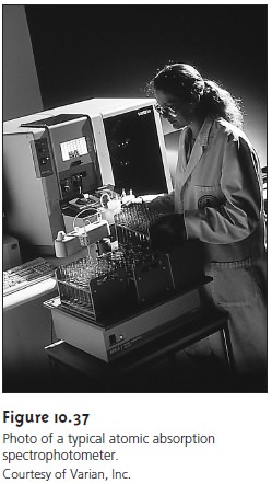
Atomic absorption spectrophotometers (Figure
10.37) are designed using either the single-beam or double-beam optics
described earlier for
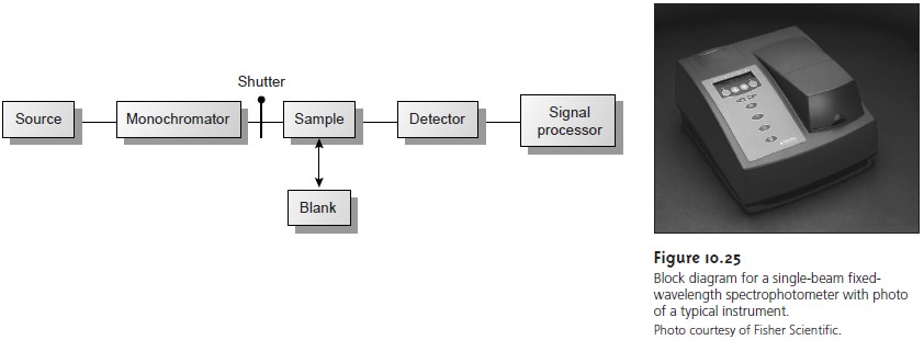
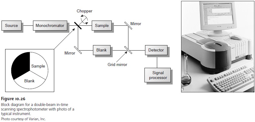
molecular absorption spec- trophotometers (see Figures 10.25 and 10.26).
There are, however,
several impor- tant differences that are considered in this section.
Atomization
The most important difference between a spectrophotometer for atomic absorption and one for molecular absorption is the need to convert
the ana- lyte into
a free atom.
The process of converting an analyte in solid, liquid,
or solu- tion form to a free gaseous
atom is called
atomization. In
most cases the sample
containing the analyte undergoes some form of sample preparation that leaves the analyte in an organic
or aqueous solution.
For this reason,
only the introduction of solution samples is considered in this text. Two general
methods of atomization are used: flame atomization and electrothermal atomization. A few elements
are atom- ized using other methods.
Flame Atomizers
In flame atomization the sample is first converted into a fine mist consisting of small droplets of solution. This is accomplished using a nebulizer assembly similar to that shown in the inset to Figure 10.38. The sample is aspirated into a spray chamber by passing a high-pressure stream consisting of one or more combustion gases, past the end of a capillary tube immersed in the sample. The im- pact of the sample with the glass impact bead produces an aerosol mist.
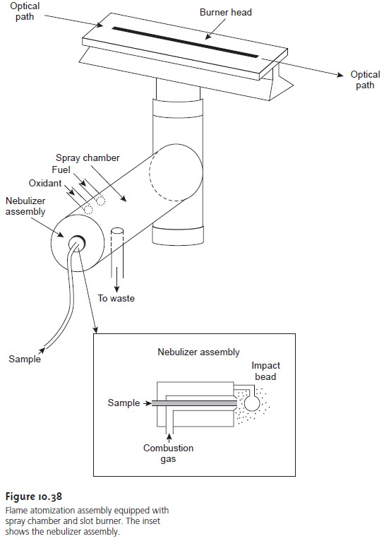
The aerosol mist mixes with the combustion gases in the spray chamber
before passing to the
burner where the flame’s thermal
energy desolvates the
aerosol mist to a dry
aerosol of small, solid
particles. Subsequently, thermal
energy volatilizes the
particles, pro- ducing a vapor consisting of molecular species, ionic species, and
free atoms.
Thermal
energy
in
flame
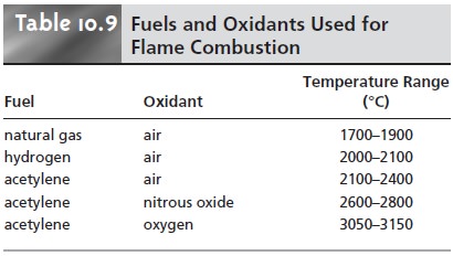
atomization is provided by the combustion of a fuel–oxidant
mixture. Common fuels and oxidants and their normal temperature ranges are listed in Table 10.9.
Of these, the air–acetylene and nitrous oxide-acetylene flames are used most frequently. Normally, the fuel and oxidant are mixed in an ap- proximately stoichiometric ratio; however, a fuel-rich mixture
may be desirable for atoms
that are easily
oxidized. The most
common design for
the burner is the slot burner shown in Figure
10.38. This burner
provides a long
path length for
monitoring absorbance and a stable flame.
The burner is mounted on an adjustable stage that allows the entire burner as- sembly to move horizontally and vertically. Horizontal adjustment is necessary to ensure that the flame is aligned with the instrument’s optical path. Vertical adjust- ments are needed to adjust the height within the flame from which absorbance is monitored.
This is important because
two competing processes affect the concen- tration of free atoms
in the flame. An increased residence time in the flame
results in a greater
atomization efficiency; thus,
the production of free atoms
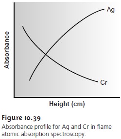
increases with height. On the other hand, longer residence times may lead to the formation of metal
oxides that absorb at a wavelength different
from that of the atom. For easily oxidized metals, such as Cr, the concentration of free atoms
is greatest just above
the burner head. For metals,
such as Ag, which are difficult to oxidize, the concen-
tration of free atoms increases steadily with height
(Figure 10.39). Other
atoms show concentration profiles
that maximize at a characteristic height.
The most common
means for introducing samples into a flame atomizer
is continuous aspiration, in which the
sample is continuously passed through the burner
while monitoring the absorbance. Continuous aspiration is sample-
intensive, typically requiring 2–5 mL of sample. Flame
microsampling provides a means
for introducing a discrete sample
of fixed volume
and is useful when the volume of sample is limited or when the sample’s matrix
is incompatible with the
flame atomizer. For
example, the continuous aspiration of a sample contain- ing a high concentration of dissolved solids,
such as sea water, may result in the build-up of solid deposits
on the burner head. These
deposits partially obstruct the flame, lowering the
absorbance. Flame microsampling is accomplished using a micropipet to place
50–250 μL of sample in a Teflon
funnel connected to the nebulizer, or by dipping
the nebulizer tubing
into the sample
for a short time. Dip sampling is usually accomplished with an automatic sampler. The signal
for flame microsampling is a transitory peak whose height
or area is proportional to the
amount of analyte
that is injected.
The principal advantage of flame atomization is the reproducibility with which the sample
is introduced into the spectrophotometer. A significant disadvantage to flame atomizers is that the efficiency of atomization may be quite
poor. This may occur for two reasons.
First, the majority
of the aerosol mist produced
during nebu- lization consists
of droplets that are too large to be carried
to the flame by the com-
bustion gases. Consequently, as much as 95% of the sample
never reaches the
flame. A second reason
for poor atomization efficiency is that the large
volume of combus- tion gases significantly dilutes
the sample. Together, these contributions to the effi- ciency of atomization reduce
sensitivity since the
analyte’s concentration in the
flame may be only 2.5 x 10⁻⁶ of that
in solution.
Electrothermal Atomizers
A significant improvement in sensitivity is achieved by using resistive heating in place of a flame. A typical electrothermal atomizer, also known as a graphite furnace, consists of a cylindrical graphite tube approximately 1-3 cm in length, and 3-8 mm in diameter (Figure 10.40).
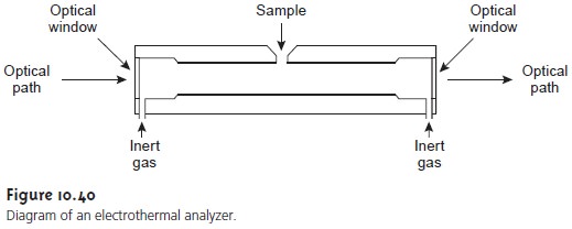
The graphite tube is
housed in an assembly that
seals the ends
of the tube
with optically transparent win- dows. The assembly
also allows for the passage
of a continuous stream of inert gas, protecting the graphite tube from
oxidation, and removing the gaseous products produced during atomization. A power supply
is used to pass a current through
the graphite tube, resulting in resistive heating.
Samples between 5 and 50 μL are injected into the graphite
tube through a small-diameter hole located at the top of the tube. Atomization is achieved in three
stages. In the first stage
the sample is dried using
a current that
raises the tempera- ture of the graphite tube to about
110 °C. Desolvation leaves the sample
as a solid residue. In the
second stage, which
is called ashing,
the temperature is increased to 350–1200 °C. At these
temperatures, any organic
material in the sample is con-
verted to CO2 and H2O, and volatile inorganic
materials are vaporized. These gases are removed
by the inert gas flow. In the final stage the sample is atomized
by rapidly increasing the temperature to 2000–3000 °C. The result is a transient ab-
sorbance peak whose height or area is proportional to the absolute
amount of ana- lyte
injected into the graphite tube. The three stages are complete in approximately
45–90 s, with most of this time
used for drying
and ashing the
sample.
Electrothermal atomization provides a significant improvement in
sensitivity by trapping the gaseous analyte
in the small volume of the graphite
tube. The ana- lyte’s concentration in the resulting vapor
phase may be as much as 1000 times
greater than that produced by flame atomization. The improvement in sensitivity, and the
resulting improvement in detection limits,
is offset by a significant decrease in precision. Atomization efficiency is strongly
influenced by the sample’s contact
with the graphite tube, which
is difficult to control reproducibly.
Miscellaneous Atomization Methods
A few elements
may be atomized by a chemi-
cal reaction that produces a volatile product.
Elements such as As, Se, Sb, Bi, Ge, Sn, Te,
and Pb form volatile hydrides
when reacted with NaBH4 in acid. An inert gas carries the volatile hydrides
to either a flame or to a heated quartz observation tube situated in the optical
path. Mercury is determined by the cold-vapor method in which it is reduced
to elemental mercury
with SnCl2. The volatile Hg is carried
by an inert gas to an unheated observation tube situated in the instrument’s optical path.
Related Topics