Chapter: Embedded Systems
I/O Devices
I/O DEVICES
In this
section we survey some input and output devices commonly used in embed-ded
computing systems. Some of these devices are often found as on-chip devices in
micro-controllers; others are generally implemented separately but are still
commonly used. Looking at a few important devices now will help us understand
both the requirements of device interfacing in this chapter and the uses of
devices in programming in this and later chapters.
Timers and Counters
Timers and
counters are distinguished from one another largely by their use, not
their
logic. Both are built from adder logic with registers to hold the
current
value,
with an increment input that adds one to the current register value. However, a
timer has its count connected to a periodic clock signal to measure time
intervals, while a counter has its count input connected to an aperiodic signal
in order to count the number of occurrences of some external event. Because the
same logic can be used for either purpose, the device is often called a counter/timer
.
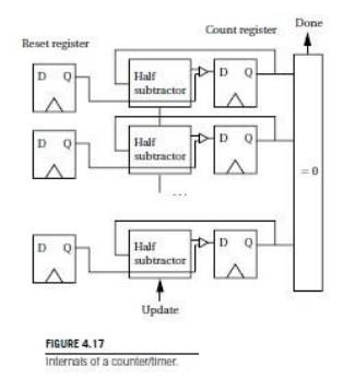
Figure shows enough of the internals of a
counter/timer to illustrate its operation. An n-bit counter/timer uses an n-bit
register to store the current state of the count and an array of half subtractors
to decrement the count when the count signal
is
asserted. Combinational logic checks when the count equals zero; the done output signals the zero count. It
is often useful to be able to control the time-out, rather than require exactly
2n events to occur. For this purpose, a reset register provides the value with
which the count register is to be loaded. The counter/timer provides logic to
load the reset register. Most counters provide both cyclic and acyclic modes of
operation. In the cyclic mode, once the counter reaches the done state, it is
automatically reloaded and the counting process continues. In acyclic mode, the
counter/timer waits for an explicit signal from the microprocessor to resume
counting.
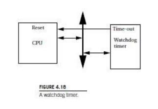
A watchdog
timer is an I/O device that is used for internal operation of a system.
As shown in Figure 4.18, the watchdog timer is connected into the CPU bus and
also to the CPU’s reset line. The CPU’s software is designed to periodically
reset the watchdog timer, before the timer ever reaches its time-out limit. If
the watchdog timer ever does reach that limit, its time-out action is to reset
the processor. In that case, the presumption is that either a software flaw or
hardware problem has caused the CPU to misbehave. Rather than diagnose the problem,
the system is reset to get it operational as quickly as possible.
Keyboards
A
keyboard is basically an array of switches, but it may include some internal
logic to help simplify the interface to the microprocessor. In this chapter, we
build our understanding from a single switch to a microprocessor-controlled
keyboard.
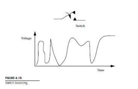
A switch
uses a mechanical contact to make or break an electrical circuit. The major
problem with mechanical switches is that they bounce as shown in Figure 4.19.
When the switch is depressed by pressing on the button attached to the switch’s
arm, the force of the depression causes the contacts to bounce several times
until they settle down. If this is not corrected, it will appear that the
switch has been pressed several times, giving false inputs. A hardware
debouncing circuit can be built using a one-shot timer. Software can also be
used to debounce switch inputs. A raw keyboard can be assembled from several
switches. Each switch in a raw keyboard has its own pair of terminals, making
raw keyboards impractical when a large number of keys is required.
More
expensive keyboards, such as those used in PCs, actually contain a
microprocessor to preprocess button inputs. PC keyboards typically use a 4-bit
microprocessor to provide the interface between the keys and the computer. The
microprocessor can provide debouncing, but it also provides other functions as
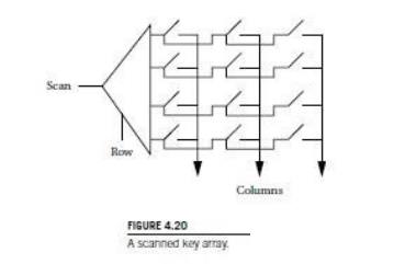
well. An encoded keyboard uses some code to represent which switch is cur-
rently being depressed. At the heart of the encoded keyboard is the scanned
array of switches shown in Figure 4.20. Unlike a raw keyboard, the scanned
keyboard array reads only one row of switches at a time. The demultiplexer at
the left side of the array selects the row to be read. When the scan input is
1, that value is trans- mitted to one terminal of each key in the row. If the
switch is depressed, the 1 is sensed at that switch’s column. Since only one
switch in the column is activated, that value uniquely identifies a key. The
row address and column output can be used for encoding, or circuitry can be
used to give a different encoding.
A
consequence of encoding the keyboard is that combinations of keys may not be
represented. For example, on a PC keyboard, the encoding must be chosen so
that
combinations such as control-Q can be recognized and sent to the PC. Another
consequence is that rollover may not be allowed. For example, if you press “a,” and
then press “b” before releasing “a,” in most applications you want the keyboard
to send an “a” followed by a “b.” Rollover is very common in typing at even
modest rates. A naive implementation of the encoder circuitry will simply throw
away any character depressed after the first one until all the keys are
released. The keyboard microcontroller can be programmed to provide n- key rollover , so that rollover keys
are sensed, put on a stack, and transmitted in sequence as keys are released.
Touchscreens
A
touchscreen is an input device overlaid on an output device. The touchscreen
registers the position of a touch to its surface. By overlaying this on a
display, the user can react to information shown on the display.
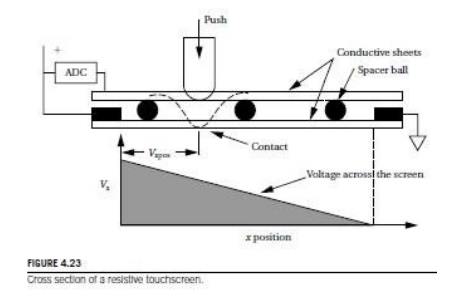
The two
most common types of touchscreens are resistive and capacitive. A resistive
touchscreen uses a two-dimensional voltmeter to sense position. As shown in
Figure 4.23, the touchscreen consists of two conductive sheets separated by
spacer balls. The top conductive sheet is flexible so that it can be pressed to
touch the bottom sheet. A voltage is applied across the sheet; its resistance
causes a voltage gradient to appear across the sheet. The top sheet samples the
conductive sheet’s applied voltage at the contact point. An analog/digital
converter is used to measure the voltage and resulting position. The
touchscreen alternates between x and y position sensing by alternately applying
horizontal and vertical voltage gradients.
Related Topics