Chapter: Embedded Systems
Core of The Embedded System
CORE OF
THE EMBEDDED SYSTEM
Unit Structure
Objectives
1 Introduction
2Core of embedded systems
General
purpose and domain specific processor.
Microprocessors
Microcontrollers.
Digital signal processors
Application Specific Integrated Circuits. (ASIC)
Programmable logic devices(PLD’s)
Commercial off-the-shelf components(COTs)
3Sensors & Actuators
4Communication Interface
OBJECTIVES
After reading this chapter you will be able to:
Understand the
different types of core i.e processor
Understand difference
between microprocessor & microcontroller
Understand the
classification of processors based on Bus Architecture, Instruction set
Architecture and
Endianness.
Have an overview of
processors from most simple and cheap to most expensive and complex, powerful
Understand what are sensors and actuators,
communication interfaces
1 INTRODUCTION
The first two chapters attempted on explain what
an embedded system is about and what the working parts are. This chapter
attempts to go deeper and explain the core of embedded system along with other
related topics.
2 CORE
OF EMBEDDED SYSTEMS
Embedded systems are domain and application
specific and are built around a central core. The core of the embedded system
falls into any of the following categories:
General purpose and Domain Specific Processors
·
Microprocessors
·
Microcontrollers
·
Digital
Signal Processors
Application
Specific Integrated Circuits. (ASIC)
Programmable
logic devices(PLD’s)
Commercial
off-the-shelf components (COTs)
2.1
GENERAL
PURPOSE AND DOMAIN
SPECIFIC PROCESSOR.
Almost 80%
of the embedded systems are processor/ controller based.
The processor may be
microprocessor or a microcontroller or digital signal processor, depending on
the domain and application.
2.1.1MICROPROCESSORS
·
A
microprocessor is a silicon chip representing a central processing unit.
·
A
microprocessor is a dependent unit and it requires the combination of other
hardware like memory, timer unit, and interrupt
controller, etc. for proper functioning.
·
Developers
of microprocessors.
o Intel – Intel
4004 – November 1971(4-bit).
o Intel – Intel 4040.
o Intel – Intel
8008 – April 1972.
o Intel – Intel
8080 – April 1974(8-bit).
o Motorola – Motorola 6800.
o Intel – Intel
8085 – 1976.
Zilog - Z80 – July 1976.
·
Architectures
used for processor design are Harvard or Von-Neumann.
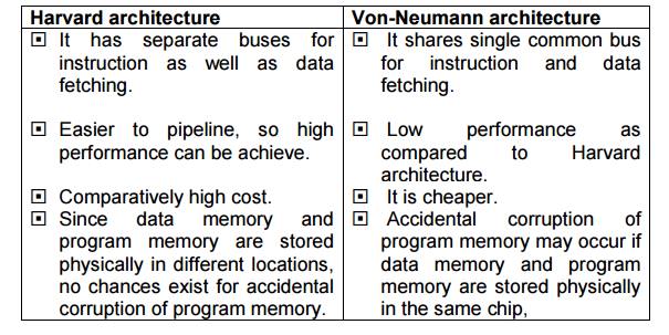
Harvard
architecture
•It has separate buses for instruction as well
as data fetching.
•Easier to pipeline, so high performance can be
achieve.
•Comparatively high cost.
•Since data memory and program memory are stored
physically in different locations, no chances exist for accidental corruption
of program memory.
Von-Neumann
architecture
•It shares single common bus for instruction and
data fetching.
•Low performance as compared to Harvard
architecture.
•It is cheaper.
•Accidental corruption of program memory may
occur if data memory and program memory are stored physically in the same chip,
RISC and CISC are the two common Instruction Set
Architectures (ISA) available for processor design.
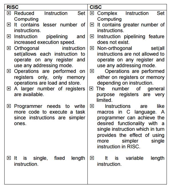
RISC
• Reduced Instruction Set Computing
•It contains lesser number of instructions.
•Instruction pipelining and increased execution
speed.
•Orthogonal instruction set(allows each
instruction to operate on any register and use any addressing mode.
•Operations are performed on registers only,
only memory operations are load and store.
•A larger number of registers are available.
•Programmer needs to write more code to execute
a task since instructions are simpler ones.
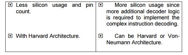
•It is single, fixed length instruction.
•Less silicon usage and pin count.
•With Harvard Architecture.
CISC
•Complex Instruction Set Computing
•It contains greater number of instructions.
•Instruction pipelining feature does not exist.
•Non-orthogonal set(all instructions are not
allowed to operate on any register and use any addressing mode.
• Operations are performed either on registers
or memory depending on instruction.
•The number of general purpose registers are
very limited.
• Instructions are like macros in C language. A
programmer can achieve the desired functionality with a single instruction
which in turn provides the effect of using more simpler single instruction in
RISC.
• It is variable length instruction.
• More silicon usage since more additional decoder logic is required to implement the complex instruction decoding.
• Can be Harvard or Von- Neumann Architecture.
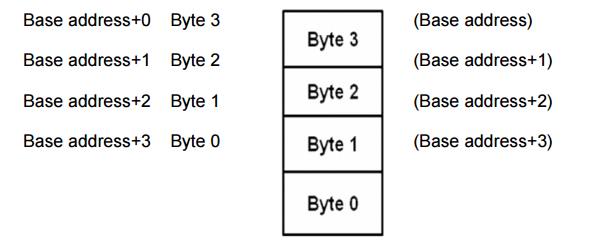
Endiannes
o Endianness specifies the order which the data is
stored in the memory by processor operations in a multi
byte system.
o
Based on Endiannes processors can be of two
types:
Little
Endian Processors
Big Endian
Processors
Little-endian means lower order data byte is
stored in memory at the lowest address and the higher order data byte at the
highest address. For e.g, 4 byte long integer Byte3, Byte2, Byte1, Byte0 will
be store in the memory as follows:
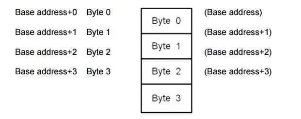
Big-endian means the higher order data byte is
stored in memory at the lowest and the lower order data byte at the highest
address. For e.g. a 4 byte integer Byte3, Byte2, Byte1, Byte0 will be stored in
the memory as follows:
2.1.2 MICROCONTROLLERS.
A
microcontroller is a highly integrated chip that contains a CPU, scratch pad
RAM, special and general purpose register arrays,on chip ROM/FLASH memory for program
storage , timer and interrupt control units and dedicated I/O ports.
Texas
Instrument’s TMS 1000 Is considered as the world’s first microcontroller.
Some
embedded system application require only 8 bit controllers whereas some
requiring superior performance and computational needs demand 16/32 bit
controllers.
The
instruction set of a microcontroller can be RISC or CISC.
Microcontrollers
are designed for either general purpose application requirement or domain
specific application requirement.
2.1.3
Digital Signal Processors
DSP are
powerful special purpose 8/16/32 bit microprocessor designed to meet the
computational demands and power constraints of today’s embedded audio, video
and communication applications.
DSP are 2
to 3 times faster than general purpose microprocessors in signal processing
applications. This is because of the architectural difference between DSP and
general purpose microprocessors.
DSPs implement algorithms in hardware which speeds
up
the execution whereas
general purpose processor
implement
the algorithm in software and the speed of
execution depends primarily on the clock for the
processors.
DSP
includes following key units:
Program memory: It is a memory for storing the program required by DSP to process the data.
Data memory: It is a working memory for storing
temporary variables and data/signal to be processed.
Computational engine: It performs the signal processing in accordance with the stored program
memory computational engine incorporated many specialized arithmetic units and
each of them operates simultaneously to increase the execution speed. It also
includes multiple hardware shifters for shifting operands and saves execution
time.
I/O unit: It acts as an interface between the outside world and DSP. It is responsible for capturing signals to be processed
and delivering the processed signals.
Examples: Audio video signal processing,
telecommunication and multimedia applications.
SOP(Sum of Products) calculation, convolution,
FFT(Fast Fourier Transform), DFT(Discrete Fourier Transform), etc are some of
the operation performed by DSP.
2.2. Application
Specific Integrated Circuits. (ASIC)
ASICs is a
microchip design to perform a specific and unique applications.
Because of
using single chip for integrates several functions there by reduces the system
development cost.
Most of
the ASICs are proprietary (which having some trade name) products, it is
referred as Application Specific Standard Products(ASSP).
As a
single chip ASIC consumes a very small area in the total system. Thereby helps
in the design of smaller system with high capabilities or functionalities.
The
developers of such chips may not be interested in revealing the internal detail
of it .
2.2. Programmable
logic devices(PLD’s)
A PLD is an electronic component. It used to
build digital circuits which are reconfigurable.
A logic gate has a fixed function but a PLD does
not have a defined function at the time of manufacture.
PLDs offer customers a wide range of logic
capacity, features, speed, voltage characteristics.
PLDs can be reconfigured to perform any number
of functions at any time.
A variety of tools are available for the
designers of PLDs which are inexpensive and help to develop, simulate and test
the designs.
PLDs having following two major types.
1) CPLD(Complex Programmable Logic Device):
CPLDs offer much smaller amount of logic up to
1000 gates.
2) FPGAs(Field Programmable Gate Arrays):
It offers highest amount of performance as well
as highest logic density, the most features.
Advantages
of PLDs :-
PLDs offer
customer much more flexibility during the design cycle.
PLDs do
not require long lead times for prototypes or production parts because PLDs are
already on a distributors shelf and ready for shipment.
PLDs can
be reprogrammed even after a piece of equipment is shipped to a customer
2.3 Commercial off-the-shelf components(COTs)
A
Commercial off the Shelf product is one which is used 'as-is'.
The COTS
components itself may be develop around a general purpose or domain specific
processor or an ASICs or a PLDs.
The major
advantage of using COTS is that they are readily available in the market, are
chip and a developer can cut down his/her development time to a great extent
The major
drawback of using COTS components in embedded design is that the manufacturer
of the COTS component may withdraw the product or discontinue the production of
the COTS at any time if rapid change in technology occurs.
Advantages of COTS:
Ready to
use
Easy to
integrate
Reduces
development time
Disadvantages of COTS:
No
operational or manufacturing standard (all proprietary)
Vendor or
manufacturer may discontinue production of a particular COTS product
3. SENSORS
& ACTUATORS
Sensor
A Sensor
is used for taking Input
It is a
transducer that converts energy from one form to
another
for any measurement or control purpose
Ex. A
Temperature sensor
Actuator
Actuator
is used for output.
It is a
transducer that may be either mechanical or electrical which converts signals
to corresponding physical actions.
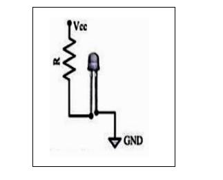
Ex. LED
(Light Emitting Diode)
LED is a
p-n junction diode and contains a CATHODE
and
ANODE
For
functioning the anode is connected to +ve end of power supply and cathode is
connected to –ve end of power supply.
The
maximum current flowing through the LED is limited by connecting a RESISTOR in
series between the power supply and LED as shown in the figure below
There are
two ways to interface an LED to a microprocessor/microcontroller:
The Anode of LED is connected to the port pin
and cathode to Ground : In
this approach the port pin sources the
current to the LED when it is at logic high(ie. 1).
The Cathode of LED is connected to the port pin
and Anode to Vcc : In this
approach the port pin sources the current
to the LED when it is at logic high (ie. 1). Here the port pin sinks the
current and the LED is turned ON when the port pin is at Logic low (ie. 0)
4. COMMUNICATION
INTERFACES
For any embedded system, the communication
interfaces can broadly classified into:
On board Communication Interfaces
These are used for
internal communication of the embedded system i.e: communication between
different components present on the system.
Common examples of
onboard interfaces are:
Inter
Integrated Circuit (I2C)
Serial
Peripheral Interface (SPI)
Universal
Asynchronous Receiver Transmitter (UART)
1-Wire
Interface
Parallel
Interface
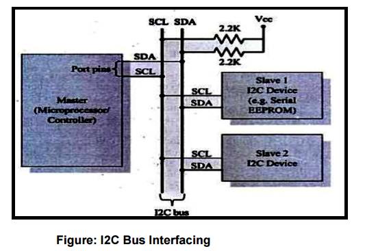
Example :Inter Integrated Circuit (I2C)
• It is
synchronous
• Bi-directional, half duplex , two wire serial interface bus
• Developed by Phillips semiconductors in 1980
It comprises of two buses :
Serial clock –SCL
Serial Data – SDA
SCL generates synchronization clock pulses
SDA transmits data serially across devices
I2C is a shared bus system to which many devices can be connected
Devices connected by I2C can act as either master or slave
The master device is responsible for controlling communication by initiating/ terminating data transfer.
Devices acting as slave wait for commands from the master and respond to those commands.
External
or Peripheral Communication Interfaces
These are
used for external communication of the embedded system i.e: communication of
different components present on the system with external or peripheral
components/devices.
Common
examples of external interfaces are:
RS-232 C
& RS-485
Universal
Serial Bus (USB)
IEEE 1394
(Firewire)
Infrared
(IrDA)
Bluetooth
Wi-Fi
Zig Bee
General
Packet Radio Service (GPRS)
Example: RS-232 C & RS-485
It is
wired, asynchronous, serial, full duplex communication
RS 232
interface was developed by EIA (Electronic Industries Associates) In early
1960s
RS 232 is
the extension to UART for external communications
RS-232
logic levels use:
+3 to +25
volts to signify a "Space" (Logic 0) and
-3 to -25
volts to signify a "Mark" (logic 1).
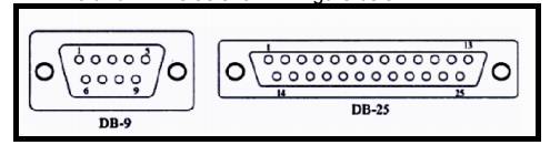
RS 232
supports two different types of connectors :
DB 9 and DB 25 as shown in figure below
RS 232
interface is a point to point communication interface and the devices involved
are called as Data Terminating Equipment (DTE) And Data
Communications
Terminating Equipment (DCE)
Embedded
devices contain UART for serial transmission and generate signal levels as per
TTL/CMOS logic.
A level
translator IC (like Max 232) is used for converting the signal lines from
UART to RS
232 signal lines for communication.
The vice
versa is performed on the receiving side.
Converter
chips contain converters for both transmitters and receivers
RS 232 is
used only for point to point connections
It is
susceptible to noise and hence is limited to short distances only
RS 422 is
another serial interface from EIA.
It
supports multipoint connections with 1 transmitter and 10 receivers.
It
supports data rates up to 100Kbps and distance up to 400 ft
RS 485 is
enhanced version of RS 422 and supports up to 32 transmitters and 32
receivers
Related Topics