Chapter: Embedded Systems
The Embedded System Design Process
THE EMBEDDED SYSTEM DESIGN PROCESS
Overview
of the embedded system design process aimed at two objectives. First,it will
give us an introduction to the various steps in embedded system design before
we delve into them in more detail. Second, it will allow us to consider the
design methodology itself.Figure 1.1 summarizes the major steps in the
embedded system design process.In this top–down view,we start with the system requirements
in the next step comes Specification.
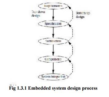
Top–down
Design—we will begin with the most abstract description of the system and conclude
with concrete details. The alternative is a bottom–up view in which we start with components to build a system.
Bottom–up design steps are shown in the figure as dashed-line arrows. We need
bottom–up design because we do not have perfect insight into how later stages
of the design process will turn out. During the design process we have to
consider the major goals of the design such as
■ manufacturing
cost;
■ performance
(both overall speed and deadlines); and
■ power
consumption.
Design
steps are detailed below:
A.Requirements:
Requirements may be functional or nonfunctional.
We must capture the basic functions of the embedded system, but functional
description is often not sufficient. Typical nonfunctional requirements
include:
1. Performance: The speed
of the system is often a major consideration both for the usability of the
system and for its ultimate cost. Performance may be a combination of soft
performance metrics such as approximate time to perform a user-level function
and hard deadlines by which a particular operation must be completed.
2. Cost: The
target cost or purchase price for the system is almost always a consideration.
Cost
typically has two major components:
o Manufacturing cost includes the cost
of components and assembly;
o NonRecurring
engineering (NRE) costs include the personnel and
other costs of
designing
the system.
3.
Physical size and weight: The
physical aspects of the final system can vary greatly depending upon
the application. e.g) An industrial control system for an assembly line may be
designed to fit into a standard-size rack with no strict limitations on weight.
But a handheld device typically has tight requirements on both size and weight
that can ripple through the entire system design.
Power
consumption: Power, of course, is important in battery-powered
systems and is often important in other applications as well. Power can be
specified in the requirements stage in terms of battery life.
mock-up. The
mock-up may use canned data to simulate functionality in a restricted demonstration, and it may be
executed on a PC or a workstation. But it should give the customer a good idea of how the system will
be used and how the user can react to it. Physical,nonfunctional models of devices
can also give customers a better idea of characteristics such as size and
weight.
e.g) Requirements analysis of a GPS moving map
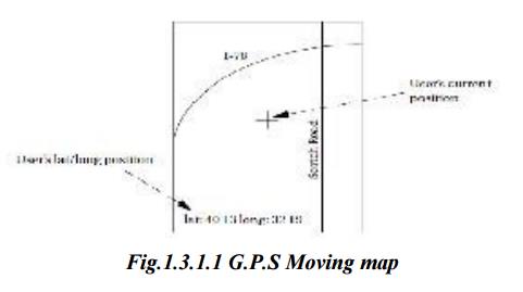
The
moving map is a handheld device that displays for the user a map of the terrain
around the user’s current position; the map display changes as the user and the
map device change position.
The
moving map obtains its position from the GPS, a satellite-based navigation
system.
Ø The
moving map display might look something like the following figure
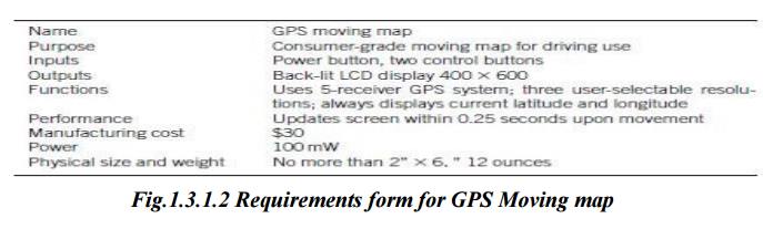
■ Functionality: This system is designed for
highway driving and similar uses, not nautical or aviation uses that require more specialized databases and
functions. The system should show major roads and other landmarks available in
standard topographic databases.
■ User interface: The screen should have at least
400_600 pixel resolution. The device should be controlled by no more than three buttons.
■ Performance: The map should scroll smoothly.
Upon power-up, a display should take no more
than one second to appear, and the system should be able to verify its
position and display the current map within 15 s.
■ Cost: The selling cost (street price)
of the unit should be no more than $100.
■ Physical size and weight: The
device should fit comfortably in the palm of the hand.
■ Power consumption: The
device should run for at least eight hours on four AA batteries.
2 B. Specification
The
specification is more precise—it serves as the contract between the customer
and the architects. The specification should be understandable enough so that
someone can verify that it meets system requirements and overall expectations
of the customer. It should also be unambiguous. the specification must be
carefully written so that it accurately reflects the customer’s requirements
and does so in a way that can be clearly followed during design. A
specification of the GPS system would include several components:
Data
received from the GPS satellite constellation.
Map
Data
User
Interface
Operations
that must be performed to satisfy customer requests. Background actions
required to keep the system running, such as operating the GPS receiver. UML, a
language for describing specifications
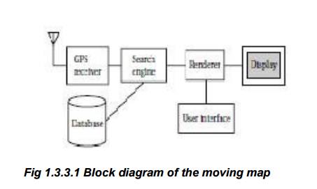
C. Architecture Design
The
specification does not say how the system does things, only what the system
does. Describing how the system implements those functions is the purpose of
the architecture. Figure 1.3 shows a sample system architecture in the form of
a block diagram that shows major operations and data flows among them.
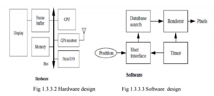
Many
implementation details should we refine that system block diagram into two
block diagrams: one for hardware and another for software. These two more
refined block diagrams are shown in Figure 1.4.The hardware block diagram clearly
shows that we have one central CPU surrounded by memory and I/O devices. In
particular, we have chosen to use two memories: a frame buffer for the pixels
to be displayed and a separate program/data memory for general use by the CPU .
D. Designing Hardware and Software Components
The
component design effort builds those components in conformance to the
architecture and specification. The components will in general include both
hardware—FPGAs, boards, and so on—and software modules. Some of the components
will be ready-made. In the moving map, the GPS receiver is a good example of a
specialized component that will nonetheless be a predesigned, standard
component. We can also make use of standard software modules. One good example is
the topographic database.
E. System Integration
The
components built are put together and see how the system works. If we debug
only a few modules at a time, we are more likely to uncover the simple bugs and
able to easily recognize them. Only by fixing the simple bugs early will we be
able to uncover the more complex or obscure bugs.
Related Topics