Chapter: Embedded Systems
Bus communication Protocols: 12C, USB, CAN, PCI
SERIAL BUSCOMMUNICATION PROTOCOLS– I2C
Interconnecting number of device circuits, Assume flash memory, touch screen, ICs for measuring temperatures and ICs for measuring pressures at a number of processes in a plant.
_ ICs mutually network through a common synchronous serial bus I2C An 'Inter Integrated Circuit' (I2C) bus,a popular bus for these circuits.
_Synchronous Serial Bus Communication for networking
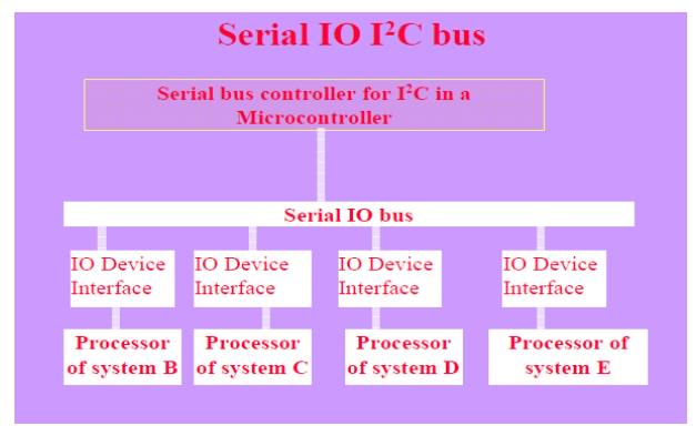
_ Each specific I/O synchronous serial device may be connected to other using specific interfaces, for example, with I/O device using I2C controller
_ I2C Bus communication− use of only simplifies the number of connections and provides a common way (protocol) of connecting different or same type of I/O devices using synchronous serial communication
IO I2C Bus
_ Any device that is compatible with a I2Cbus can be added to the system(assuming an appropriate device driver program is available), and a I2C device can be integrated into any system that uses that I2C bus.
Originally developed at Philips Semiconductors
Synchronous Serial Communication 400kbps up to 2 m and 100 kbps for longer distances
Three I2C standards
1. Industrial 100 kbps I2C,
2. 100 kbps SM I2C,
3. 400 kbps I2C
I2C Bus
_ The Bus has two lines that carry its signals— one line is for the clock and one is for bi-directional data.
_ There is a standard protocol for the I2Cbus.
Device Addresses and Master in the I2C bus
_ Each device has a 7-bit address using which the data transfers take place. _ Master can address 127 other slaves at an instance.
_ Master has at a processing element functioning as bus controller or a microcontroller with I2C (Inter Integrated Circuit) bus interface circuit.
Slaves and Masters in the I2C bus
_ Each slave can also optionally has I2C (Inter Integrated Circuit) bus controller and processing element.
_ Number of masters can be connected on the bus.
_ However, at an instance, master is one, which initiates a data transfer on SDA(serial data) line and which transmits the SCL (serial clock) pulses. From master, a data frame has fields beginning from start bit
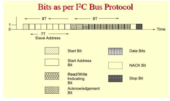
Synchronous Serial Bus Fields and its length
_ First field of 1 bit─ Start bit similar to one in an UART
_ Second field of 7 bits─ address field. It defines the slave address, which is being sent the data frame (of many bytes) by the master
_ Third field of 1 control bit─ defines whether a read or write cycle is in progress
_ Fourth field of 1 control bit─ defines whether is the present data is an acknowledgment (from slave)
_ Fifth field of 8 bits─ I2C device data byte
_ Sixth field of 1-bit─ bit NACK (negative acknowledgement) from the receiver. If active then acknowledgment after a transfer is not needed from the slave, else acknowledgement is expected from the slave
_ Seventh field of 1 bit ─ stop bit like in an UART
Disadvantage of I2C bus
• Time taken by algorithm in the hardware that analyzes the bits throughI2C in case the slave hardware does not provide for the hardware that supports it.
• Certain ICs support the protocol and certain do not.
• Open collector drivers at the master need a pull-up resistance of 2.2 K on each line
SERIAL BUSCOMMUNICATION PROTOCOLS - CAN
Distributed
Control Area Network example - a network of embedded systems in automobile
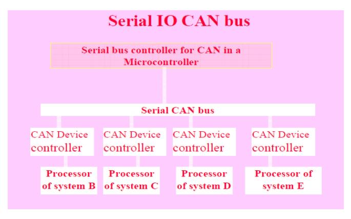
_ CAN-bus
line usually interconnects to a CAN controller between line and host at the node.
It gives the input and gets output between the physical and data link layers at
the host node.
_ The CAN
controller has a BIU (bus interface unit consisting of buffer and driver),
protocol controller, status-cum control registers, receiver-buffer and message
objects. These units connect the host node through the host interface circuit
Three
standards:
1. 33 kbps
CAN,
2. 110 kbps
Fault Tolerant CAN,
3. 1 Mbps
High Speed CAN
CAN protocol
There is
a CAN controller between the CAN line and the host node.
_ CAN
controller ─BIU (Bus Interface Unit)consisting of a buffer and driver
_ Method
for arbitration─ CSMA/AMP(Carrier Sense Multiple Access with Arbitration on
Message Priority basis)
Each Distributed Node Uses:
• Twisted
Pair Connection up to 40 m –for bi-directional data
• Line,
which pulls to Logic 1 through a resistor between the line and + 4.5V to +12V.
• Line Idle
state Logic 1 (Recessive state)
• Uses a
buffer gate between an input p in and the CAN line
• Detects
Input Presence at the CAN line pulled down to dominant (active) state logic 0
(ground ~ 0V) by a sender to the CAN line
• Uses a
current driver between the output pin and CAN line and pulls line down to
dominant
(active)
state logic 0(ground ~ 0V) when sending to the CAN line Protocol defined start
bit followed by six fields of frame bits Data frame starts after first
detecting that dominant state is not present at the CAN line with logic 1 (R
state) to 0 (D state transition) for one serial bit interval
• After
start bit, six fields starting from arbitration field and ends with seven
logic0s end-field
• 3-bit
minimum inter frame gap before next start bit (R→ D transition) occurs
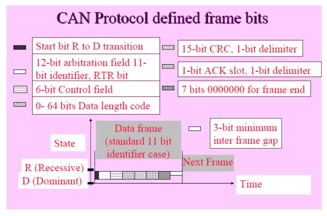
Protocol
defined First field in frame bits
_ First
field of 12 bits ─'arbitration field.
_ 11-bit
destination address and RTR bit (Remote Transmission Request)
_
Destination device address specified in an11-bit sub-field and whether the data
byte being sent is a data for the device or a request to the device in 1-bit
sub-field.
_ Maximum
211 devices can connect a CAN controller in case of 11-bit address
fieldstandard11-bit address standard CAN
_
Identifies the device to which data is being sent or request is being made.
_ When
RTR bit is at '1', it means this packet is for the device at destination address.
If this bit is at '0' (dominant state) it means, this packet is a request for
the data from the device.
Protocol
defined frame bits Second field _ Second field of 6 bits─ control field.
The first
bit is for the identifier‘ sextension.
_ The
second bit is always '1'.
_ The
last 4 bits specify code for data Length
_ Third
field of 0 to 64 bits─ Its length depends on the data length code in the control
field.
• Fourth
field (third if data field has no bit present) of 16 bits─ CRC (Cyclic Redundancy
Check) bits.
• The
receiver node uses it to detect the errors, if any, during the transmission
• Fifth
field of 2 bits─ First bit 'ACK slot'
• ACK = '1'
and receiver sends back '0' in this slot when the receiver detects an error in
the
reception.
• Sender
after sensing '0' in the ACK slot, generally retransmits the data frame.
• Second
bit 'ACK delimiter' bit. It signals the end of ACK field.
• If the
transmitting node does not receive any acknowledgement of data frame within a
Specified
time slot, it should retransmit.
Sixth field of 7-bits ─ end- of- the frame specification and
has seven '0's
SERIAL BUSCOMMUNICATION PROTOCOLS– USB
USB Host
Applications Connecting
• flash
memory cards,
• pen-like
memory devices,
• digital
camera,
• printer,
• mouse-device,
• Pocket PC,
• video
games,
• Scanner
Universal Serial Bus (USB)
_ Serial
transmission and reception between host and serial devices
_ The
data transfer is of four types: (a)Controlled data transfer, (b) Bulk data transfer,
(c) Interrupt driven data transfer, (d) Iso-synchronous transfer
_ A bus
between the host system and inter connected number of peripheral devices
USB Protocol Features
_ Maximum
127 devices can connect a host.
_ Three
standards: USB 1.1 (a low speed1.5 Mbps 3 meter channel along with a high speed
12 Mbps 25 meter channel),USB 2.0 (high speed 480 Mbps 25meter channel), and
wireless USB(high speed 480 Mbps 3 m)
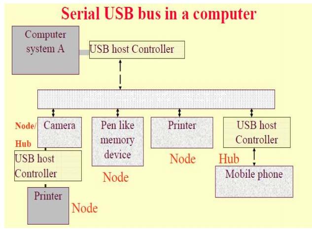
Host connection to the devices or nodes
_ Using
USB port driving software and host controller,
_ Host
computer or system has a host controller, which connects to a root hub. _ A hub
is one that connects to other nodes or hubs.
_ A tree-
like topology
USB Device features
_ Can be
hot plugged (attached), configured and used, reset, reconfigured and used
_
Bandwidth sharing with other devices: Host schedules the sharing of bandwidth
among the attached devices at an instance.
_ Can be
detached (while others are in operation) and reattached. _ Attaching and
detaching USB device or host without rebooting
USB device descriptor
_ Has
data structure hierarchy as follows:
_ It has
device descriptor at the root, which has number of configuration descriptors,
which has number of interface descriptor and which has number of end point
descriptor.
Powering USB device
_ A
device can be either bus-powered or self- powered.
_ In
addition, there is a power management by software at the host for USB ports
USB protocol
_ USB bus
cable has four wires, one for+5V, two for twisted pairs and one for ground.
_
Termination impedances at each end as per the device-speed.
_
Electromagnetic Interference (EMI)-shielded cable for the 15 Mbps USB devices.
_ Serial
signals NRZI (Non Return to Zero (NRZI)
_ The
synchronization clock encoded by inserting synchronous code (SYNC)field before
each USB
packet
_
Receiver synchronizes its bits recovery clock continuously
USB Protocol
• A polled
bus
• Host
controller regularly polls the presence of a device as scheduled by the
software.
• It sends
a token packet.
• The token
consists of fields for type, direction, USB device address and device end-point
number.
• The
device does the handshaking through a handshake packet, indicating successful
or unsuccessful transmission.
• A CRC
field in a data packet permitserror detection
USB supported three types of pipes
1. 'Stream'
with no USB- defined protocol. It is used when the connection is already established
and the data flow starts
2. 'Default
Control' for providing access.
3. 'Message'
for the control functions for of the device.
• Host
configures each pipe with the data bandwidth to be used, transfer service type and
buffer
sizes.
PARALLEL BUSDEVICE PROTOCOLS – PCI Bus
_
Parallel bus enables a host computer or system to communicate simultaneously
32-bit or
64-bit with other devices or systems, for example, to a network interface card
(NIC) or graphic card
Computer system PCI
• When the
I/O devices in the distributed embedded subsystems are networked all can
communicate through a common parallel bus.
• PCI
connects at high speed to other subsystems having a range of I/O devicesat very
short
distances
(<25 cm) using a parallel bus without having to implement a specific
interface for each
I/O
device.
PCI bus Applications
Connects
_ display
monitor,
_
printer,
_
character devices,
_ network
subsystems,
_ video
card,
_ modem
card,
_ hard
disk controller,
PCI bus connects
_ thin
client,
_ digital
video capture card, _ streaming displays,
_ 10/100
Base T card,
_ Card
with 16 MB Flash ROM with a router gateway for a LAN and _ Card using DEC 21040
PCI Ethernet LAN controller.
• When
the I/O devices in the distributed embedded subsystems are networked, all can
communicate through a common parallel bus.
• PCI
connects at high speed to other subsystems having a range of I/O devicesat very
short distances (<25 cm) using a parallel bus without having to implement a
specific interface for each I/O device.
PCI Bus Feature
_ 32- bit
data bus extendible to 64 bits.
_ PCI
protocol specifies the ways of interaction between the different components of
a computer.
_ A
specification version 2.1─synchronous/asynchronous throughput is up to 132/ 528
MB/s [33M × 4/ 66M× 8 Byte/s], operates on 3.3V to 5Vsignals.
_ PCI
driver can access the hardware automatically as well as by the programmer
assigned addresses.
_ Automatically
detects the interfacing systems and assigns new addresses
_ Thus,
simplified addition and deletion(attachment and detachment) of the system
peripherals.
FIFO in PCI device/card
_ Each
device may use a FIFO controller with a FIFO buffer for maximum throughput.
Identification Numbers
_ A
device identifies its address space by three identification numbers, (i) I/O port
(ii) Memory locations and (iii)Configuration registers of total 256Bwith a four
4-byte unique ID. Each PCI device has address space allocation of256 bytes to
access it by the host
Computer
PCI device identification
_ A
sixteen16-bit register in a PCI device identifies this number to let that
device auto- detect it.
_ Another
sixteen16-bit register identifies a device ID number. These two numbers let
allow the device to carry out its auto-detection by its host computer.
Peripheral Component Interconnect (PCI) Bus
_
Independent from the IBM architecture.
_ Number
of embedded devices in a computer system use PCI _ Three standards for the
devices interfacing with the PC
_ PCI
32bit/33 MHz, and 64bit/66 MHz
_ PCI
Extended (PCI/X) 64 bit/100 MHz ,
_ Compact
PCI (cPCI) Bus
Two super speed versions
_ PCI
Super V2.3 264/528 MBps 3.3V (on64- bit bus), and 132/264 (on 32-bit bus)and _ PCI-X
Super V1.01a for 800MBps 64- bitbus 3.3Volt.
PCI bridge
_ PCI bus
interface switches a processor communication with the memory bus to PCI bus.
_ In most systems, the processor has a single data
bus that connects to a switch module
_ Some
processors integrate the switch module onto the same integrated circuit asthe
processor to reduce the number of chips required to build a system and thus the
system cost.
_
Communicates with the memory through a memory
bus (a set of address, control and data buses), a dedicated set of wires
that transfer data between these two systems.
_ A
separate I/O bus connects the PCI switch
to the I/O devices.
Advantage of Separate memory and I/O buses
_ I/O
system generally designed for maximum flexibility, to allow as many different
I/O devices as possible to interface to the computer
_ Memory
bus is designed to provide the maximum-possible bandwidth between the processor
and the memory system.
PCI-X (PCI extended)
• 133 MBps
to as much as 1 GBps
• Backward
compatible with existing
PCI cards
• Used in
high bandwidth devices(Fiber Channel, and processors that are part of a cluster
and Gigabit Ethernet)
• Maximum
264 MBps throughput, uses 8,16, 32, or 64 bit transfers
• 6U cards
contain additional pins for user defined I/Os
Live
insertion support (Hot-Swap),
• Supports
two independent buses on the back plane (on different connectors)
• Supports
Ethernet, Infiniband, and StarFabric support (Switched fabric based systems) Compact
PCI (cPCI)
Each PCI
device on Bus
_ Perform
a specific function,
_ May
contain a processor and software to perform a specific function.
_ Each
device has the specific memory address-range, specific
interrupt-vectors(pre-assigned or auto configured) and the device I/O port
addresses.
_ A bus
of appropriate specifications and protocol interfaces these to the host computer
system or compute
Configuration address space
_ Unique
feature of PCI bus unique feature is its configuration address space.
PCI controller Features
• Accesses
one device at a time
• All the
devices within host device or system can share the I/O port and memory
addresses, but
cannot
share the configuration registers
• Device
cannot modify other configuration registers but can access other device
resources or share the work or assist the other device
• If
there are reasons for doing it so, a PCI driver can change the default bootup
assignments on configuration transactions.
PCI Device Initialization
A device
can initialize at booting time
• Avoids
any address collision
• Device on
boot up disables its interrupt and closes its door to its address space except
to the configuration registers space
PCI BIOS (Basic Input-Output System)
Performs the configuration transactions and then, memory and address spaces automatically map to the address space in the device hosting system
Related Topics