Chapter: 11th 12th std standard Class Physics sciense Higher secondary school College Notes
Transistor amplifier - Operating point, Working
Transistor amplifier
The important function of a transistor is the amplification. An
amplifier is a circuit capable of magnifying the amplitude of weak signals. The
important parameters of an amplifier are input impedance, output impedance,
current gain and voltage gain. A good design of an amplifier circuit must
possess high input impedance, low output impedance and high current gain.
Operating point
For the given values of the load resistance Rc and supply
voltage Vcc, two points A (VCC, 0) and B (0,Vcc/Rc) are located on
the axes of VCE and IC respectively, of the output characteristics of the
transistor (Fig ).
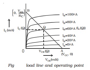
Joining A and B, load line AB is obtained. The point of intersection Q of this line
in the active region of the
output characteristics with a
suitable value of the base current IB, such that the output voltage is
symmetrical is
Working
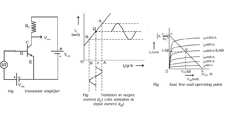
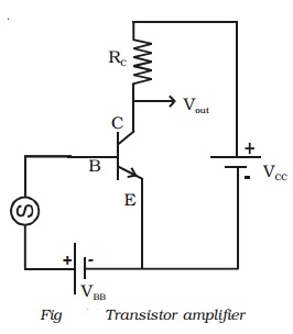
A basic circuit of an amplifier in common emitter mode with NPN
transistor is shown in Fig. The emitter-base junction is forward biased by a
supply voltage VBB. The input ac signal to be amplified is applied between
base and emitter of the transistor. RC is the load resistance.
The amplifying action of a transistor can be explained as
follows. When the a.c. signal is not applied, the base current is available in
small quantity in microamperes, which is represented by OP and the
corresponding collector current in milliamperes is represented by PQ (Q is the
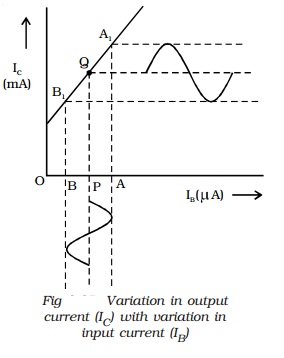
operating point). When the ac signal voltage is applied, the potential
difference between the base and emitter changes continuously. This results in
increase of base current (IB) from OP to OA, then decrease of base
current from OA to OP (during positive half cycles of he input a.c. voltage)
and then to PB and once again increase from OB to OP (during negative half
cycle of the input a.c. voltage) for each cycle of the input signal voltage.
This variation in base current is reflected in the collector current as shown
in Fig. The collector current (IC) increases from PQ to AA1,
falls from AA1 to BB1and again increases from BB1
to PQ. Thus a variation in the base current in micro amperes produces a
corresponding variation in the collector current in milliamperes. This produces
a corresponding potential difference across RC. The increase of
potential difference across Rc makes a decrease in the output
voltage.
Therefore, there is always a
phase reversal of 180o between the input and output voltages in CE
amplifier.
Related Topics