Chapter: 11th 12th std standard Class Physics sciense Higher secondary school College Notes
Spectrometer
Spectrometer
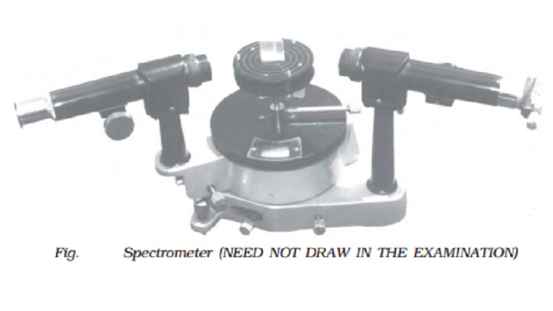
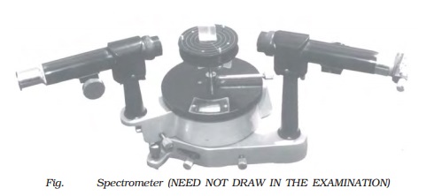
The spectrometer is an
optical instrument used to study the spectra of different sources of light and
to measure the refractive indices of materials (Fig. ). It consists of
basically three parts. They are collimator, prism table and Telescope.
Collimator
The collimator is an
arrangement to produce a parallel beam of light. It consists of a long
cylindrical tube with a convex lens at the inner end and a vertical slit at the
outer end of the tube. The distance between the slit and the lens can be
adjusted such that the slit is at the focus of the lens. The slit is kept
facing the source of light. The width of the slit can be adjusted. The
collimator is rigidly fixed to the base of the instrument.
Prism table
The prism table is
used for mounting the prism, grating etc. It consists of two circular metal
discs provided with three levelling screws. It can be rotated about a vertical
axis passing through its centre and its position can be read with verniers V1
and V2. The prism table can be raised or lowered and can be fixed at
any desired height.
Telescope
The telescope is an
astronomical type. It consists of an eyepiece provided with cross wires at one
end of the tube and an objective lens at its other end co-axially. The distance
between the objective lens and the eyepiece can be adjusted so that the
telescope forms a clear image at the cross wires, when a parallel beam from the
collimator is incident on it.
The telescope is
attached to an arm which is capable of rotation about the same vertical axis as
the prism table. A circular scale graduated in half degree is attached to it.
Both the telescope and
prism table are provided with radial screws for fixing them in a desired
position and tangential screws for fine adjustments.
Adjustments of the
spectrometer
The following
adjustments must be made before doing the experiment with spectrometer.
(i) Adjustment of the
eyepiece
The telescope is
turned towards an illuminated surface and the eyepiece is moved to and fro
until the cross wires are clearly seen.
(ii) Adjustment of the
telescope
The telescope is
adjusted to receive parallel rays by turning it towards a distant object and
adjusting the distance between the objective lens and the eyepiece to get a
clear image on the cross wire.
(iii) Adjustment of the
collimator
The telescope is
brought along the axial line with the collimator. The slit of the collimator is
illuminated by a source of light. The distance between the slit and the lens of
the collimator is adjusted until a clear image of the slit is seen at the cross
wires of the telescope. Since the telescope is already adjusted for parallel
rays, a well defined image of the slit can be formed, only when the light rays
emerging from the collimator are parallel.
(iv) Levelling the
prism table
The prism table is adjusted or levelled to be in horizontal
position by means of levelling screws and a spirit level.
Determination of the
refractive index of the material of the prism
The preliminary adjustments of the telescope, collimator and the
prism table of the spectrometer are made. The refractive index of the prism can
be determined by knowing the angle of the prism and the angle of minimum
deviation.
(i) Angle of the prism (A)
The prism is placed on the prism table with its refracting edge
facing the collimator as shown in Fig . The slit is illuminated by a sodium
vapour lamp.
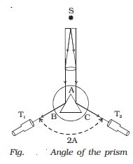
The parallel rays coming from the collimator
fall on the two faces AB and AC.
The telescope is rotated to the position T1 until the image of the slit, formed by the
reflection at the face AB is made to coincide
with the vertical cross wire of the telescope. The readings of
the verniers are noted. The telescope is then rotated to the position T2 where the image of the slit formed by the
reflection at the face AC coincides with the vertical cross wire. The readings
are again noted.
The difference between these two readings gives the angle
rotated by the telescope. This angle is equal to twice the angle of the prism.
Half of this value gives the angle of the prism A.
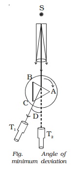
(ii) Angle of minimum
deviation (D)
The prism is placed on
the prism table so that the light from the collimator falls on a refracting
face, and the refracted image is observed through the telescope (Fig. ). The
prism table is now rotated so that the angle of deviation decreases. A stage
comes when the image stops for a moment and if we rotate the prism table
further in the same direction, the image is seen to recede and the angle of
deviation increases. The vertical cross wire of the telescope is made to coincide
with the image of the slit where it turns back. This gives the minimum
deviation position. The readings of the verniers are noted. Now the prism is
removed and the telescope is turned to receive the direct ray and the vertical
cross wire is made to coincide with the image. The readings of the verniers are
noted. The difference between the two readings gives the angle of minimum
deviation D.
The refractive index
of the material of the prism ? is calculated using the formula ? = sin((A+D) / 2) /
sin(A/2)
The refractive index
of a liquid may be determined in the same way using a hollow glass prism filled
with the given liquid.
Related Topics