Chapter: 11th 12th std standard Class Physics sciense Higher secondary school College Notes
Refraction of light
Refraction of light
When
a ray of light travels from one transparent medium into another medium, it
bends while crossing the interface, separating the two media. This phenomenon
is called refraction.
Image
formation by spherical lenses is due to the phenomenon of refraction. The laws
of refraction at a plane surface are equally true for refraction at curved
surfaces also. While deriving the expressions for refraction at spherical
surfaces, we make the following assumptions.
(i) The incident light is
assumed to be monochromatic and
(ii)
the incident pencil of light rays is very narrow and close to
the principal axis.
1 Cartesian sign
convention
The
sign convention followed in the spherical mirror is also applicable to
refraction at spherical surface. In addition to this two more sign conventions
to be introduced which are:
(i)
The power of a converging lens is positive and that of a
diverging lens is negative.
(ii)
The refractive index of a medium is always said to be positive.
If two refractions are involved, the difference in their refractive index is
also taken as positive.
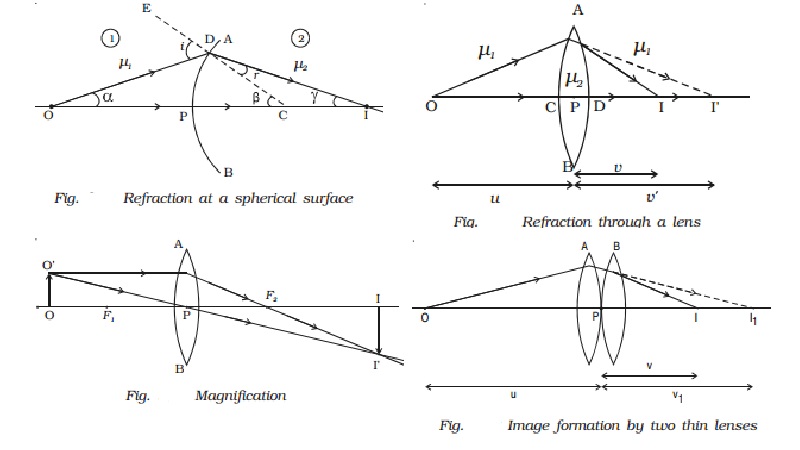
2 Refraction at a
spherical surface
Let us consider a portion of a spherical surface AB separating
two media having refracting indices ?1 and ?2 (Fig. ).
This is symmetrical about an axis passing through the centre C and cuts the
surface at P.
The point P is called the pole of the surface. Let R be the
radius of curvature of the surface.
Consider a point object O on the axis in the first medium.
Consider two rays OP and OD originating from O. The ray OP falls normally on AB and goes into the second medium,
undeviated. The ray OD falls at D very close to P. After refraction, it meets at the point I on the axis, where the
image is formed. CE is the normal
drawn to the point D. Let i and r be the angle of incidence and refraction respectively.
Let angle DOP = α, angle DCP =
β, Angle DIC = γ
Since D is close to P, the angles α, β and γ are all small. From
the Fig.
tan α = DP/PO
tan β = DP/PO
tan γ = DP/PI
α = DP/PO
β = DP/PO
γ = DP/PI
From the ∆ODC, i = α + β
??..(1)
From the ∆DCI, β = r + γ or r = β ? γ ???(2)
From Snell?s Law, ?2/ ?1 = sin i/ sin r
and for small angles of i and r, we can write, ?1 i = ?2r ...(3)
we get ?1 (α +
β) = ?2 (β − γ) or ?1
α + ?2 γ = (?2 - ?1 )β ????(4)
Substituting the values of α, β and γ in equation (4)
?1(DP/PO) + ?2 (DP/PI) = (?2 -
?1) . DP/PC
?1/PO + ?2/PI = ( ?2 - ?1 )
/PC
As the incident ray comes from left to right, we choose this
direction as the positive direction of the axis. Therefore u is negative,
whereas v and R are positive substitute PO = ?u PI = +v and PC = +R in equation
(5),
( ?1 / -u ) + (?2/v) = (?2- ?1)/R
(?2/v) - ( ?1 / u ) + = (?2- ?1)/R ???.(6)
Equation (6) represents the general equation for refraction at a
spherical surface.
If the first medium is air and the second medium is of
refractive index ?, then
(? / v) ? ( 1/u) = (? -1)/R
.3 Refraction through
thin lenses
A lens is one of the
most familiar optical devices. A lens is made of a transparent material bounded
by two spherical surfaces. If the distance between the surfaces of a lens is
very small, then it is a thin lens.
As there are two
spherical surfaces, there are two centres of curvature C1 and C2
and correspondingly two radii of curvature R1 and R2. The
line joining C1 and C2 is called the principal axis of the lens. The centre P of the thin lens which
lies on the principal aixs is called the optic centre.
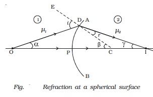
4 Lens maker?s formula
and lens formula
Let us consider a thin
lens made up of a medium of refractive index ?2 placed in a medium of refractive index ?1. Let R1 and R2 be the radii of curvature of two spherical surfaces ACB and ADB respectively and P be
the optic centre.
Consider a point
object O on the principal axis. The ray OP falls normally on the spherical
surface and goes through the lens undeviated. The ray OA falls at A very close
to P. After refraction at the surface ACB the image is formed at I′. Before it
does so, it is again refracted by the surface ADB. Therefore the final image is
formed at I as shown in Fig.
The general equation for
the refraction at a spherical surface is given by
( ?2/v ) ?
(?1/u) = (?2-?1)/R ????.(1)
For the refracting
surface ACB, from equation (1) we write
?2/v? - ?1/u = (?2-?1)/R1 ????..(2)
The image I′ acts as a
virtual object for the surface ADB and the final image is formed at I. The
second refraction takes place when light
travels from the
medium of refractive index ?2
to ?1.
For the refracting
surface ADB, from equation (1) and applying sign conventions, we have
?1/v - ?2/v? =[ (?2 - ?1)(-R2)] ????(3)
.
Adding equations (2)
and (3)
?1/v - ?2/u = (?2 - ?1
)[1/R1 - 1/R2]
Dividing the above
equation by ?1
1/v -1/u = [(?2/
?1)-1][ 1/R1 ? 1/R2 ] ???????..(4)
If the object is at
infinity, the image is formed at the focus of the lens.
Thus, for u = ∞, v =
f. Then the equation (4) becomes.
1/f = [(?2/ ?1)-1][ 1/R1
? 1/R2 ]
???????..(5)
If the refractive
index of the lens is ? and it is placed in air, ?2 = ? and ?1 = 1. So the equation (5) becomes
1/f = [?-1][ 1/R1 ? 1/R2 ] ???????..(6)
This is called the
lens maker?s formula, because it tells what curvature will be needed to make a
lens of desired focal length. This formula is true for concave lens also.
Comparing equation (4)
and (5)
We get 1/v ? 1/u =
1/f ??..(7)
which is known as the
lens formula.
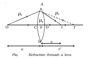
5 Magnification
Let us consider an
object OO ′ placed on the principal axis with its height perpendicular to the
principal axis as shown in Fig. The ray
OP passing through the optic centre will go undeviated. The ray O ′A parallel to
the principal axis must pass through the focus F2
. The image is formed
where O ′PI′ and AF2 I′ intersect. Draw a perpendicular from I′ to the
principal axis. This perpendicular II ′ is
the image of OO ′.
The linear or
transverse magnification is defined as the ratio of the size of the image to
that of the object.
Magnification m = Size
of the image / Size of the object = II?/OO? = h2/h1
where h1 is the height of the object and h2 is the height of the image.
From the similar right
angled triangles OO′ P and II′ P, we have II?/OO? = PI/PO
Applying sign
convention,
II′ = -h2
OO? = +h1
PI = +v
PO = -u
Substituting this in
the above equation, we get magnification
M=-h2/+h1
= +v/-u
M=+ v/u
The magnification is
negative for real image and positive for virtual image. In the case of a
concave lens, it is always positive.
Using lens formula the
equation for magnification can also be obtained as
m = h2/h1
= v//u = (f-v)/f = f/(f+u)
This equation is valid
for both convex and concave lenses and for real and virtual images.
6 Power of a lens
Power of a lens is a
measure of the degree of convergence or divergence of light falling on it. The power of a lens (P) is defined as the
reciprocal of its focal length.
P=1/f
The unit of power is
dioptre (D) : 1 D = 1 m-1. The power of the lens is said to be 1 dioptre if the focal length of the lens is 1
metre. P is positive for
converging lens and negative for diverging lens. Thus, when an optician
prescribes a corrective lens of power + 0.5 D, the required lens is a convex
lens of focal length + 2 m. A power of -2.0 D means a concave lens of focal
length -0.5 m.
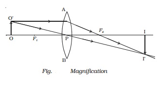
7 Combination of thin
lenses in contact
Let us consider two
lenses A and B of focal length f1 and f2 placed in contact with each other. An object
is placed at O beyond the focus of the first lens A on the common principal
axis.
The lens A produces an
image at I1 . This image I1 acts as the object for the
second lens B. The final image is produced at I as shown in Fig. Since the lenses are thin, a common optical
centre P is chosen.
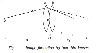
Let PO = u, object distance for the first
lens (A), PI = v, final image
distance and PI1 = v1, image distance for the
first lens (A) and also object distance for second lens (B).
For the image I1 produced by the first lens A,
1/v1 ? 1/u
= 1/f1 ????..(1)
For the final image I,
produced by the second lens B,
1/v - 1/v1 = 1/f2 ????..(2)
Adding equations (1)
and (2),
1/v ? 1/u = 1/f1
+ 1/f2 ????..(3)
If the combination is
replaced by a single lens of focal length F such that it forms the image of O
at the same position I, then
1/v - 1/u
= 1/F ????(4)
From equations (3) and
(4)
1/F = 1/f1 +
1/f2 ?????(5)
This F is the focal
length of the equivalent lens for the combination. The derivation can be
extended for several thin lenses of focal
lengths f1,
f2, f3 ... in
contact. The effective focal length of the combination is given by
1/F = 1/f1 + 1/f2 + 1/f3 + ?????.. ?..(6)
In terms of power,
equation (6) can be written as
P = P1 + P2 + P3 + .... ...(7)
Equation (7) may be
stated as follows :
The power of a
combination of lenses in contact is the algebraic sum of the powers of
individual lenses.
The combination of
lenses is generally used in the design of objectives of microscopes, cameras,
telescopes and other optical instruments.
Related Topics