Chapter: 11th 12th std standard Class Physics sciense Higher secondary school College Notes
Circuit symbol and Pin-out configuration of an OP-AMP
Operational amplifier (OP - AMP)
Linear integrated circuits are
being used in a number of electronic applications, such as in the fields like
communication, medical electronics, instrumentation control etc. An important
linear IC is an operational amplifier.
OP-AMP is a solid state device capable of sensing and amplifying
dc and ac input signals. OP-AMP is an amplifier with two inputs (differential
inputs) and a single output. OP-AMP consists of 20 transistors, 11 resistors
and one capacitor. It usually requires a positive and negative power supply
(dual power supply). This allows the output voltage to swing positive and
negative with respect to ground.
The most important
characteristics of OP-AMP are : (i) very high input impedance or even infinity
which produces negligible current at the inputs, (ii) very high gain, (iii)
very low output impedance or even zero, so as not to affect the output of the
amplifier by loading.
An OP-AMP is so named, because it
was originally designed to perform mathematical operations such as addition,
subtraction, multiplication, division, integration, differentiation etc in
analog computer. Nowdays OP-AMPs are used in analog computer operations and in
timing circuits.
Circuit symbol and Pin-out
configuration of an OP-AMP
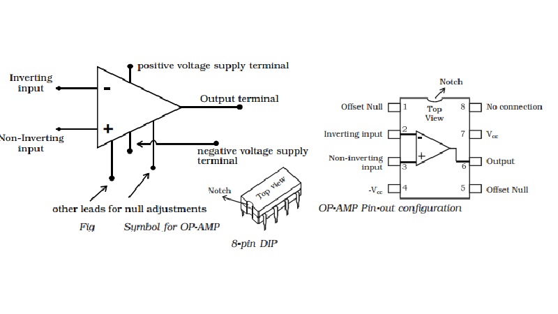
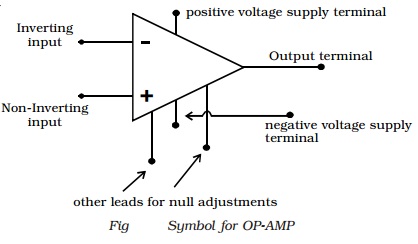
The OP - AMP is represented by a
triangular symbol as shown in Fig. It has two input terminals and one output
terminal. The terminal with negative
sign is called as the inverting input and the terminal with positive sign is called as the
non-inverting input. The input terminals are at the base of the triangle. The
output terminal is shown at the apex of the triangle.
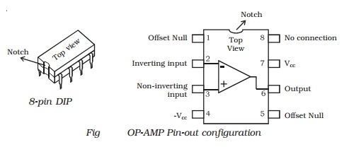
The widely used very popular type
Op-Amp IC 741, which is available in DIP. Referring to the top view of the
dual-in-package, the pin configuration of IC 741 can be described (Fig) as
follows. The top pin on the left side of the notch indicates Pin 1. The pin
number 2 is inverting input terminal and 3 is non-inverting input terminal. Pin
6 is the output terminal. A d.c. voltage or a.c signal placed on the inverting
input will be 180o out of phase at the output. A d.c. voltage or
a.c. signal placed on the non-inverting input will be inphase at the output.
Pins 7 and 4 are the power supply terminals. Terminals 1 and 5 are used for
null adjustment. Null adjustment pins are used to null the output voltage when
equal voltages are applied to the input terminals for perfect balance. Pin 8
indicates no connection.
Related Topics