Chapter: 11th 12th std standard Class Physics sciense Higher secondary school College Notes
PN junction diode as Half wave and Bridge wave rectifier
PN junction diode as rectifier
The process in which alternating voltage or alternating current
is converted into direct voltage or direct current is known as rectification.
The device used for this process is called as rectifier. The junction diode has
the property of offering low resistance and allowing current to flow through
it, in the forward biased condition. This property is used in the process of
rectification.
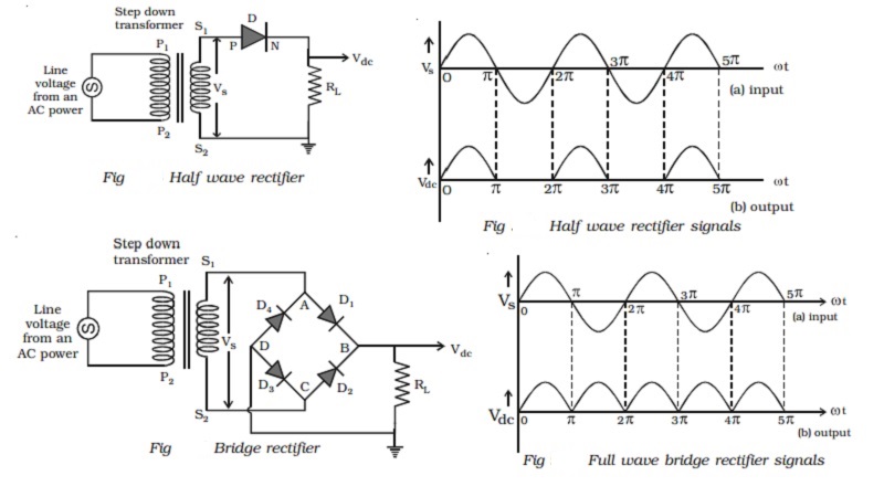
Half wave rectifier
A circuit which rectifies half of
the a.c wave is called half wave rectifier.
Fig shows the circuit for half wave rectification. The a.c.
voltage (Vs) to be rectified is obtained across the secondary ends S1
S2 of the transformer. The P-end of the diode D is connected to S1
of the secondary coil of the transformer. The N-end of the diode is connected
to the other end S2 of the secondary coil of the transformer,
through a load resistance RL. The rectified output voltage Vdc
appears across the load resistance RL.
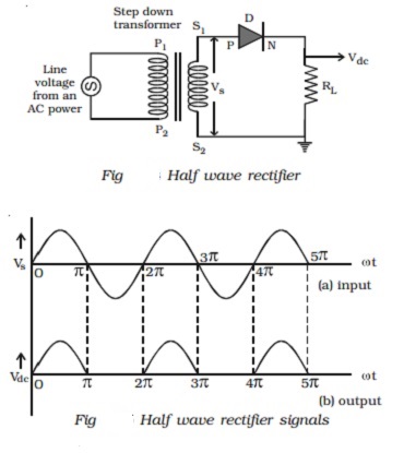
During the positive half cycle of
the input a.c. voltage Vs, S1 will be positive and the
diode is forward biased and hence it conducts.
Therefore, current flows through
the circuit and there is a voltage drop across RL. This gives the
output voltage as shown in Fig.
During the negative half cycle of
the input a.c. voltage (Vs), S1 will be negative and the
diode D is reverse biased. Hence the diode does not conduct. No current flows
through the circuit and the voltage drop across RL will be zero.
Hence no output voltage is obtained. Thus corresponding to an alternating input
signal, unidirectional pulsating output is obtained.
The ratio of d.c. power output to
the a.c. power input is known as rectifier efficiency. The efficiency of half
wave rectifier is approximately 40.6%
Bridge rectifier
A bridge rectifier is shown in
Fig. There are four diodes D1, D2, D3 and D4
used in the circuit, which are connected to form a network. The input ends A
and C of the network are connected to the secondary ends S1 and S2
of the transformer. The output ends B and D are connected to the load
resistance RL.
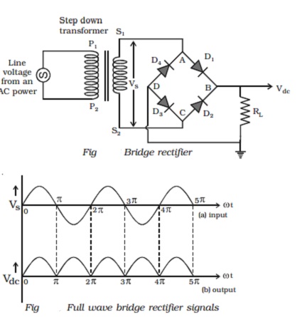
During positive input half cycle
of the a.c. voltage, the point A is positive with respect to C. The diodes D1
and D3 are forward biased and conduct, whereas the diodes D2
and D4 are reverse biased and do not conduct. Hence current flows
along S1ABDCS2 through RL. During negative
half cycle, the point C is positive with respect to A. The diodes D2
and D4 are forward biased and conduct, whereas the diodes D 1
and D3 are reverse biased and they do not conduct. Hence current
flows along S2CBDAS 1 through RL. The same
process is repeated for subsequent half cycles. It can be seen that, current
flows through RL in the same direction, during both half cycles of
the input a.c. signals. The output signal corresponding to the input signal is
shown in Fig. The efficiency of the bridge rectifier is approximately 81.2%.
Filter circuits and regulation
property of the power supply
Both in half wave and full wave
rectifiers, it is observed that the output voltage across RL varies
from zero to a maximum value. Eventhough, unidirectional current through RL
is obtained, the output voltage fluctuates. This fluctuation in output voltage
is not desirable, when pure d.c. voltage is required. Hence they must be
removed or smoothened. This can be achieved with the help of suitable networks
called filters such as capacitor filter, inductor filter etc., and we can get
almost a steady d.c. voltage. But this steady d.c. output voltage from a
rectifier is not constant due to the following reasons.
(i) As the load varies, the d.c.
output voltage is not constant. That is, as the current drawn from the
rectifier increases, the output voltage decreases and vice versa. The variation
of d.c. output voltage as a function of d.c. load current is called regulation.
The percentage of regulation = [(Vno load - Vload) /
Vload ]x
100
(ii) The d.c. output voltage
varies directly as the a.c. input voltage to the rectifier. The line voltage
from a.c. power (220 V) may not be a constant and may vary from 200 V to 240 V.
Hence the d.c. output voltage will also vary. To overcome these difficulties,
Zener diodes are used as regulators and are used along with rectifier and
filter circuits. They are called 'regulated power supplies'.
Related Topics