Chapter: 11th 12th std standard Class Physics sciense Higher secondary school College Notes
Basic OP-AMP circuits: Inverting, Non-inverting, Summing, Difference amplifier
Basic OP-AMP circuits
This section concentrates on the
principles involved with basic OP-AMP circuit viz, (i) inverting and (ii)
non-inverting amplifiers.
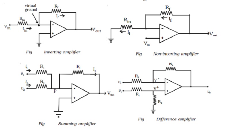
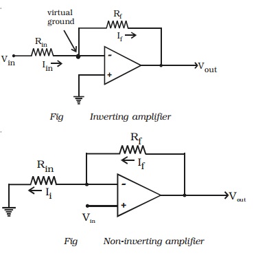
(i) Inverting amplifier
The basic OP-AMP inverting
amplifier is shown in Fig. The input voltage Vin is applied to the
inverting input through the input resistor Rin. The non inverting
input is grounded. The feedback resistor Rf is connected between the
output and the inverting input.
Since the input impedance of an
op-amp is considered very high, no current can flow into or out of the input
terminals. Therefore Iin must flow through Rf and is
indicated by If (the feedback current). Since Rin and Rf
are in series, then Iin = If. The voltage between
inverting and non-inverting inputs
is essentially equal to zero
volt. Therefore, the inverting input terminal is also at 0 volt. For this
reason the inverting input is said to be at virtual ground. The output voltage
(Vout) is taken across Rf.
It can be proved that
If=Vout/Rf
Since Iin =If ,
then
Vin/Rin =
-Vout/Rf
Rearranging the equation, we
obtain
-Vout/Vin =
Rf/Rin
∴ The voltage gain of an inverting amplifier can be expressed as
Av = -Rf/Rin
The amplifier gain is the ratio
of Rf to Rin
Finally, the output voltage can
be found by
Vout = -Rf/Rin
x Vin
The output voltage is out of
phase with the input voltage.
(ii) Non-inverting amplifier
The basic OP-AMP non-inverting
amplifier is shown in Fig. The input signal Vin is applied to the
non-inverting input terminal. The resistor Rin is connected from the
inverting input to ground. The feedback resistor Rf is connected between
the output and the inverting input.
Resistors Rf and Rin
form a resistive ratio network to produce the feedback voltage (VA)
needed at the inverting input. Feedback voltage (VA) is developed
across Rin. Since the potential at the inverting input tends to be
the same as the non-inverting input (as pointed out with the description of
virtual ground), Vin = VA.
Since VA = Vin,
the gain of the amplifer can be expressed as
Av = Vou t
![]() V A
V A
However, VA is
determined by the resistance ratio of Rin and Rf ; thus,
VA=[Rin/(Rf/Rin)]
Vout
Av=1+(Rf/Rin)
Finally, the output voltage can
be found by, Vout = (1+Rf/Rin)Vin
It is seen that the input and
output voltages are in phase
(iii) Summing amplifier
The summing amplifier provides an
output voltage equal to the algebraic sum of the input voltages.
Fig shows an inverting amplifier,
used to sum two input voltages. The input voltages v1 and v2
are applied through the resistors R1 and R2 to the
summing junction (P) and Rf is the feedback resistor. At the point P,
i1 + i2 =if
Since the voltage at the point P
is ideally 0
(V1/R1) +
(V2/R2) =(Vout/Rf)
Hence the output voltage,
Vout=-[(RfV1/R1)
+(RfV2/R2) ]
If R1 = R2
= Rf = R, then vout = - (v1
+ v2)
Hence the output voltage is equal
to the sum of the input voltages and the circuit acts as a summing amplifier.
The negative sign indicates that OP-AMP is used in the inverting mode.
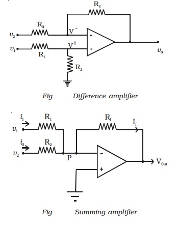
(iv)Difference amplifier
The difference amplifier is shown
in Fig. The output voltage can be obtained by using superposition principle. To
find the output voltage v01 due to v1 alone, assume that
v2 is shorted to ground. Then
V+ = R2V1
/ R1+R2
Therefore, with both inputs
present, the output is
V0 = V01 +
V02
= (R3+R4 / R3)
(R2/R1+R2) V1
- (R4/R3)V2
If R1 = R2
= R3 = R4 = R
then vo = v1 - v2
If all the external resistors are
equal, the voltage difference amplifier functions as a voltage subtractor.
Related Topics