Chapter: 11th 12th std standard Class Physics sciense Higher secondary school College Notes
Amplitude modulation (AM): Modulation factor, Analysis, Advantages, Limitations
Modulation
In radio broadcasting, it is necessary to send
audio frequency signal (eg. music, speech etc.) from a broadcasting station
over great distances to a receiver. The music, speech etc., are converted into
audio signals using a microphone. The energy of a wave increases with
frequency. So, the audio frequency (20 - 20000 Hz) is not having large amount
of energy and cannot be sent over long distances. The radiation of electrical
energy is practicable only at high frequencies e.g. above 20 kHz. The high
frequency signals can be sent through thousands of kilometres with
comparatively small power.
Therefore, if audio signal is to be transmitted
properly, the audio signal must be superimposed on high frequency wave called
carrier. The resultant waves are known as modulated waves and this process is
called as modulation. This high frequency wave (Radio frequency wave) is
transmitted in space through antenna. At the receiver end, the audio signal is
extracted from the modulated wave by the process called demodulation. The audio
signal is then amplified and reproduced into sound by the loud speaker.
A high frequency radio wave is used to carry
the audio signal. On adding the audio signal to carrier, any one of the
characteristics namely amplitude or frequency or phase of the carrier wave is
changed in accordance with the intensity of the audio signal. This process is
known as modulation and may be defined as the process of changing amplitude or
frequency or phase of the carrier wave in accordance with the intensity of the
signal. Some of the modulation process namely,
(i) amplitude modulation,
(ii) frequency modulation and
(iii) phase modulation
Amplitude modulation (AM)
When the amplitude of high frequency carrier
wave is changed in accordance with the intensity of the signal, the process is
called amplitude modulation.
In the amplitude modulation, only the amplitude of the carrier wave
is changed. The frequency and the phase of the carrier wave remains constant.
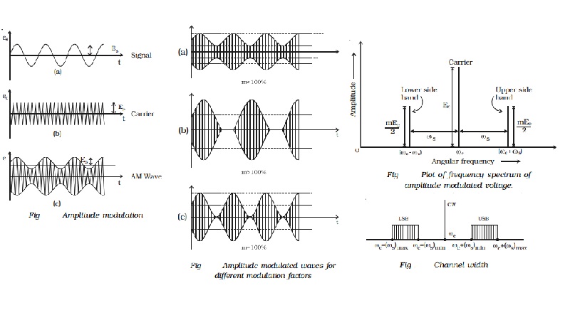
Fig shows the principle of amplitude modulation.
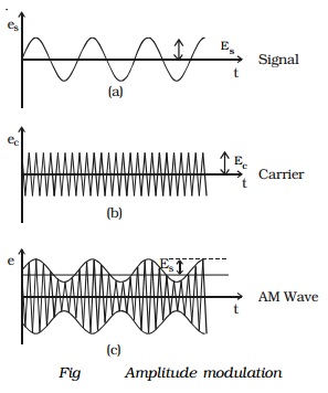
Fig a shows the audio electrical signal of frequency fs. Fig b shows a carrier
wave of constant amplitude with frequency fc.
Fig c is the amplitude modulated wave. It is to be noted that the
amplitudes of both positive and negative half cycles of carrier wave are
changed in accordance with the signal. Thus the amplitude of the modulated wave
possesses the frequency of the audio signal wave.
Modulation factor
An important term in amplitude modulation is modulation factor
which describes the extent to which the amplitude of the carrier wave is
changed by the audio signal. It is defined as the ratio of the change of
amplitude in carrier wave after modulation to the amplitude of the unmodulated
carrier wave.
i.e. modulation factor, m = Amplitude change of carrier wave after modulation / Amplitude of
carrier wave before modulation
m = Signal
amplitude / Carrier amplitude
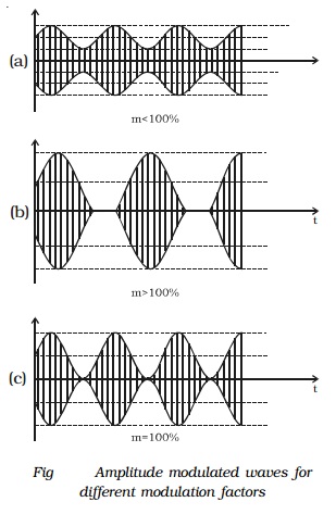
Modulation factor determines
the strength and quality of the transmitted signal. When the modulation factor m < 1, the amount of carrier amplitude varia-tion is small
(Fig a). Consequently, the audio signal being transmitted will not be very
strong. When the modulation factor m > 1, distortion is produced in the
transmitted wave as shown in Fig b.
Hence, the signal wave is not exactly reproduced. For effective
modulation, the degree of modulation should never exceed 100 %.
Analysis of amplitude modulated wave
A carrier wave may be represented as,
ec
= Ec cos ωct ������ (1)
where ec
, Ec and ωc represent the instantaneous voltage, amplitude
and angular frequency of the carrier wave respectively.
In amplitude modulation, the amplitude Ec of the carrier wave is varied in accordance with the
intensity of the audio signal as shown in Fig . The modulating signal may
be represented as,
es = Es
cosωst ���.(2)
where es,
Es and ωs represent instantaneous voltage, amplitude and angular frequency
of the signal respectively.
Amplitude modulated wave is obtained by varying
Ec of equation (1) in
accordance with Es. Thus,
amplitude modulated wave is,
e = (Ec + Es
cosωst ) cosωct
e = Ec[ 1+(Es/Ec) cosωst] cosωct = Ec[1+m cosωst] cosωct
where m is the modulation factor which is equal to Es/Ec
∴ e = Eccos ωct + mEccos ωct
. cosωst �����(3)
= Eccos ωct + (mEc/2)( ωc
+ ωs)t + + (mEc/2)( ωc - ωs)t ��..(4)
This expression shows that the modulated wave
contains three components:
1.
Ec cos ωct : This
component is same as the carrier wave.
2.
mE2c cos (ωc + ωs)t : This component has a
frequency greater than that of the carrier and is called as the Upper Side Band
(USB).
3.
mE2c cos (ωc - ωs)t : This component has a
frequency lesser than that of the carrier and is called as the Lower Side Band
(LSB).
Frequency spectrum
The lower side band term and upper side band
term are located in the frequency spectrum on either side of the carrier at a
frequency interval of ωs as shown in Fig . The magnitude of both the upper
and lower side bands is m2
times the carrier amplitude Ec.
If the modulation factor m is equal
to unity, then each side band has amplitude equal to half of the carrier
amplitude.
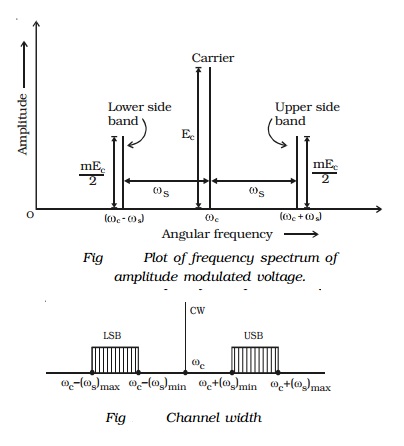
Bandwidth
However, in a broadcasting station, the modulating signal is the
human voice or music which contains waves with
a frequency range of 300 - 3000 Hz. Each of these waves has its own side bands.
The upper side band (USB), in fact, contains all sum components of the signal
and carrier frequency whereas lower side band (LSB) contains the difference
components, as shown in Fig .
The channel width is given by the difference
between extreme frequencies i.e. between maximum frequency of USB and minimum
frequency of LSB.
Channel width = 2 � maximum
frequency of the modulating signal = 2 � (fs)max
Advantages
(i)
Easy transmission and reception
(ii)Lesser bandwidth requirements
(iii)
Low cost
Limitations
(i)
Noisy reception : In an AM
wave, the signal appears in the amplitude
variations of the carrier. Practically, all the natural and man made noises
consists of electrical amplitude disturbances. As a radio receiver cannot
distinguish between amplitude variation that represent noise and those that
contain the desired signal, the reception is generally noisy.
(ii)
Low efficiency : In AM,
useful power is available in the side bands,
since they contain signals. The sideband power for an AM wave is low. Hence the
efficiency of AM is low.
(iii)
Small operating range : Due to
low efficiency of amplitude modulation,
transmitters employing this method have a small operating range i.e. the
messages cannot be transmitted over long distances.
Related Topics