Chapter: 11th 12th std standard Class Physics sciense Higher secondary school College Notes
Zener diode and Zener diode as voltage regulator
Zener diode
Zener diode is a reverse biased
heavily doped semiconductor (silicon or germanium) PN junction diode, which is
operated exclusively in the breakdown region.
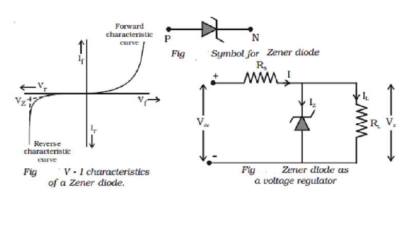
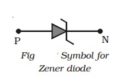
The symbol of a Zener diode is
shown in Fig. For normal operation of a Zener diode, in breakdown region, the
current through the diode should be limited by an external circuit. Hence the
power dissipated across the junction is within its power-handling capacity.
Unless this precaution is observed, a large current will destroy the diode.
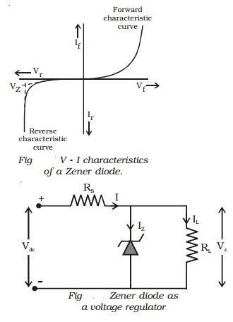
The V-I characteristic curve for
the Zener diode is shown in Fig. It can be seen from the figure, that, as the
reverse voltage applied to the PN junction is increased, at a particular
voltage, the current increases enormously from its normal cut off value. This
voltage is called zener voltage or breakdown voltage (Vz).
Zener diode as voltage regulator
To maintain a constant voltage
across the load, even if the input voltage or load current varies, voltage
regulation is to be made. A Zener
diode working in the breakdown region can act as voltage regulator.
The circuit in which a Zener
diode is used for maintaining a constant voltage across the load RL is shown in
Fig. The Zener diode in reverse biased condition is connected in parallel with
the load RL. Let Vdc be the unregulated dc voltage and Vz be Zener voltage
(regulated output voltage). Rs is the current limiting resistor. It is chosen
in such a way that the diode operates in the breakdown region.
Inspite of changes in the load
current or in the input voltage, the Zener diode maintains a constant voltage
across the load. The action of the circuit can be explained as given below.
(i) load current varies, input voltage is constant : Let us consider that the load
current increases. Zener current hence decreases, and the current through the
resistance Rs is a constant. The output voltage is Vz = Vdc
- IRs, since the total current I remains constant, output voltage
remains constant.
(ii) input voltage varies : Let us consider that the input
voltage Vdc increases. Now the current through Zener increases and
voltage drop across Rs increases in such a way that the load voltage
remains the same. Thus the Zener diode acts as a voltage regulator.
Related Topics