Chapter: Civil : Structural dynamics of earthquake engineering
How the response spectrum is constructed
How the response spectrum is constructed
Assume for any earthquake ground motion record uĖĖg
(t ) is available.
1. Numerically
define the ground acceleration uĖĖg ( t
) coordinates at every 0.02 s.
2. Select
natural vibration period and damping factor Ļ for a SDOF system.
3. Compute
the deformation response u(t) of the SDOF system to the ground
motion uĖĖg ( t ) by any of the
numerical methods discussed in previous pages.
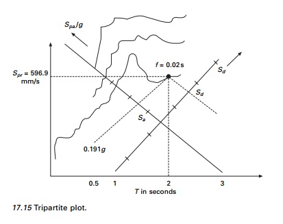
4. Determine
umax peak value of u(t).
5. Sd
=
umax; Spv = (2Ļ/Tn) Sd;
Spa = (2Ļ/Tn)2
Sd.
6. Repeat
steps 2 to 5 for a range of Tn and Ļ covering all the possible
systems of engineering interest.
7. Present
these results as three different spectra or all spectra on one sheet.
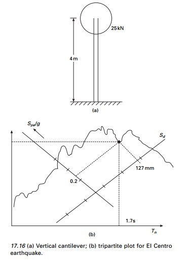
Example 17.3
A 4 m long vertical cantilever
100 mm internal diameter steel pipe supports 25 kN weight attached on the top
as shown in Fig. 17.16a. Do = 115 mm, Di =
100 mm, I = 3.676 Ć 106
mm 4 E = 200 Ć 106
kN/m2. Determine the peak deflection; bending stress due
to El, Centro ground motion.
= [ 3 Ć 200 Ć 10
6 Ć 10
3 Ć 3.676
Ć 10 ā6 ]/ 64
= 34.46 Ć 103 N/m
Total weight of the pipe (weight /m =
0.01875 kN/m) = 0.01875 Ć 4 = 0.075 kN Compared
with the top weight, the pipe weight is very small and can be
neglected.
W = 25 kN
= 25 000
N
The stress calculation exceeded
the limit, hence the designer decided to increase the size of the pipe as D0
= 220 mm; Di = 200 mm; I = 3.645 Ć 107 mm4. Comment on the advantage or
disadvantage of using bigger pipes.
k = 3EI/l3
k = 341.71
kN/mm
m = 2548 kg
The above example points out an
important difference between the response of structures due to earthquake
excitation and a fixed value of static force. In the static case, the stress
decreases by increasing the size of the member. In the case of earthquake
excitation the increase in frequency shortens the natural period from 1.7 to
0.54 s which for this spectrum increases the inertia force. Increase or
decrease in stress depends on section modulus.
Example 17.4
A single storey reinforced
concrete (RC) building (see Fig. 17.17a) is idealized for this purpose of
structural analysis as a mass-less frame supporting a dead load (DL) of 50 kN
on the beam level. The frame is 8 m wide and 4 m high. Each column and beam
have a 250 mm square section. Assuming Ļ = 5%, determine peak response of the frame due to El Centro
ground motion. In particular determine the peak lateral deflection at the beam
level and plot the diagram of bending moment at the instant of peak response.
Solution
I = 121 Ć 250 4 = 3.256 Ć 108 mm 4 ;
E = 30 Ć 10 6 kN/m 2
![]()
The beam is not rigid. The stiffness of the beam has to be
taken into account.
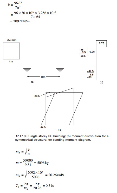
Ļ = 0.05 spa
= 0.76g sd = 17 mm (read from spectrum) static force = m a
= 50 Ć 0.76 = 38 kN
Consider
half of the frame due to symmetry
Stiffness of beam = 6I/L = 6/8 = 0.75 (for
Nylorās moment distribution)
Stiffness of column = I/h = 1/4 =0.25
Sway
moment at top and bottom = 19 Ć 2 = 38
kN/m
Moment distribution for half of
the frame is shown in Fig. 17.17b and the bending moment diagram is shown in
Fig. 17.17c.
Example 17.5
The frame shown in Fig. 17.18 is
for use in a building to be located on sloping ground. The beams are made much
stiffer than columns and can be assumed to be rigid. The cross-section of the
columns is 250 mm square but their lengths are 4 m and 8 m respectively.
Determine the base shear in the two columns, at the instant of peak response
due to El Centro ground motion. Assume damping as 5% of critical damping.
Solution
Since the beam is rigid, the stiffness of columns can be taken
as
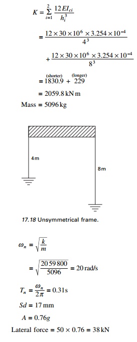
Force
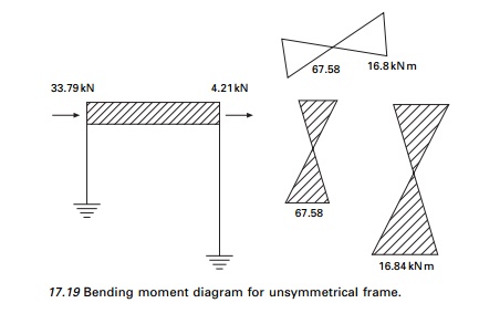
shared by long column = 38 ā 33.79 = 4.21 kN
The shear in columns as well as
bending moment diagram are shown in Fig. 17.19.
Observe that both columns go through equal deflection. The
stiffer column carries greater force than the flexible column. Sometimes this
basic principle is not recognized in building design, leading to unanticipated
damage to the stiffer structure.
Related Topics